How to Refresh your 200-4r Pump
By: Bob Koch
Note: Bob originally posted this on TurboBuick and more recently on Ihadav8 after the pictures disappeared on his original post. This is an in-depth and very informative write-up for those who want to know how it should properly be done. My thanks to Bob for giving permission to post it here as well.

PREFACE: THIS INFORMATION
IS NOT INTENDED TO BE TAKEN AS GOSPEL. THIS IS ONE PERSON'S WAY OF DOING
THINGS, SOME WILL DISAGREE WITH SOME OF IT, I'LL TRY TO POINT OUT ANYTHING THAT
FALLS UNDER BUILDER PREFERENCE. None of this will be news to any of the veteran
builders, but I'm doing this by request to help the average "guy in his garage"
get his pump built as properly as can be done without machining the housings. I
got good at these back when I worked full time at a trans shop doing 700r4
pumps. Thankfully for us, most parts interchange except the housings themselves,
which greatly helps part availability and cost. Let's not forget that the 200-4r
predated the 700r4 by three years, so the early build 200s are GM's first use of
this style pump. which brings me to the first area of discussion.
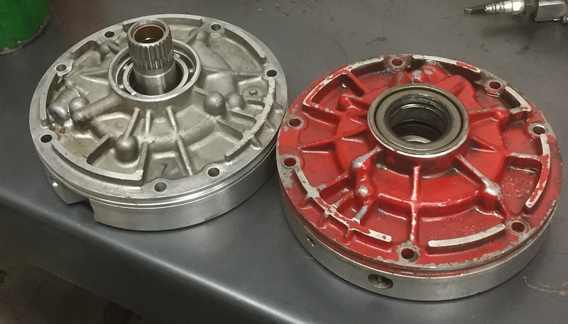
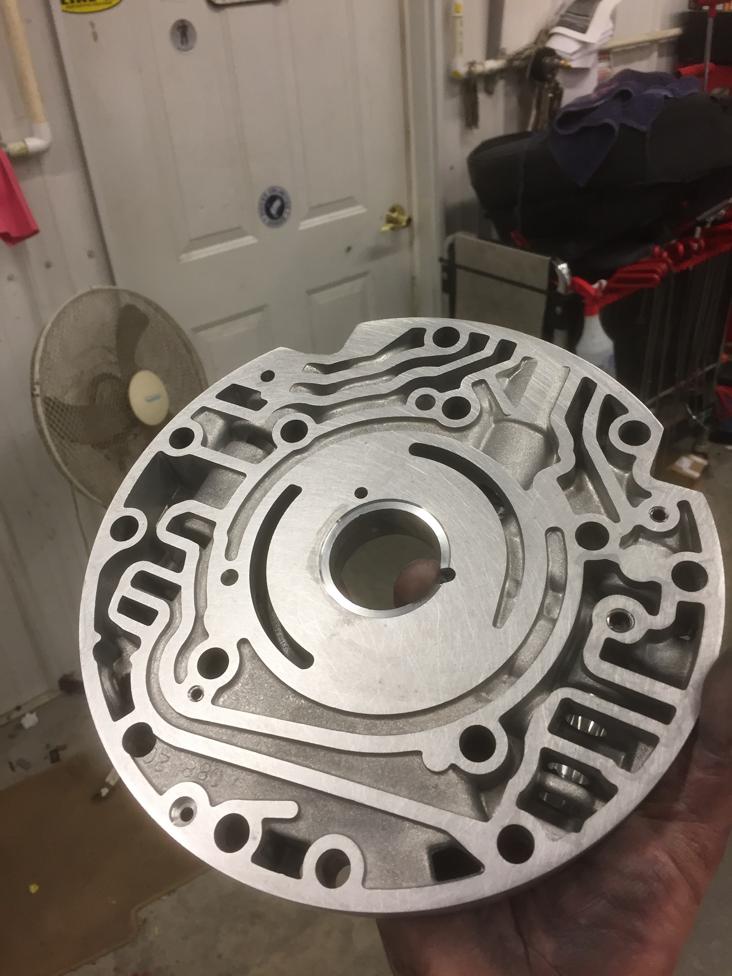
What pump
castings do you have and what's the difference? Early build pumps and pump
covers are 149/150 casting number (ignore the red paint,it's the only early pump
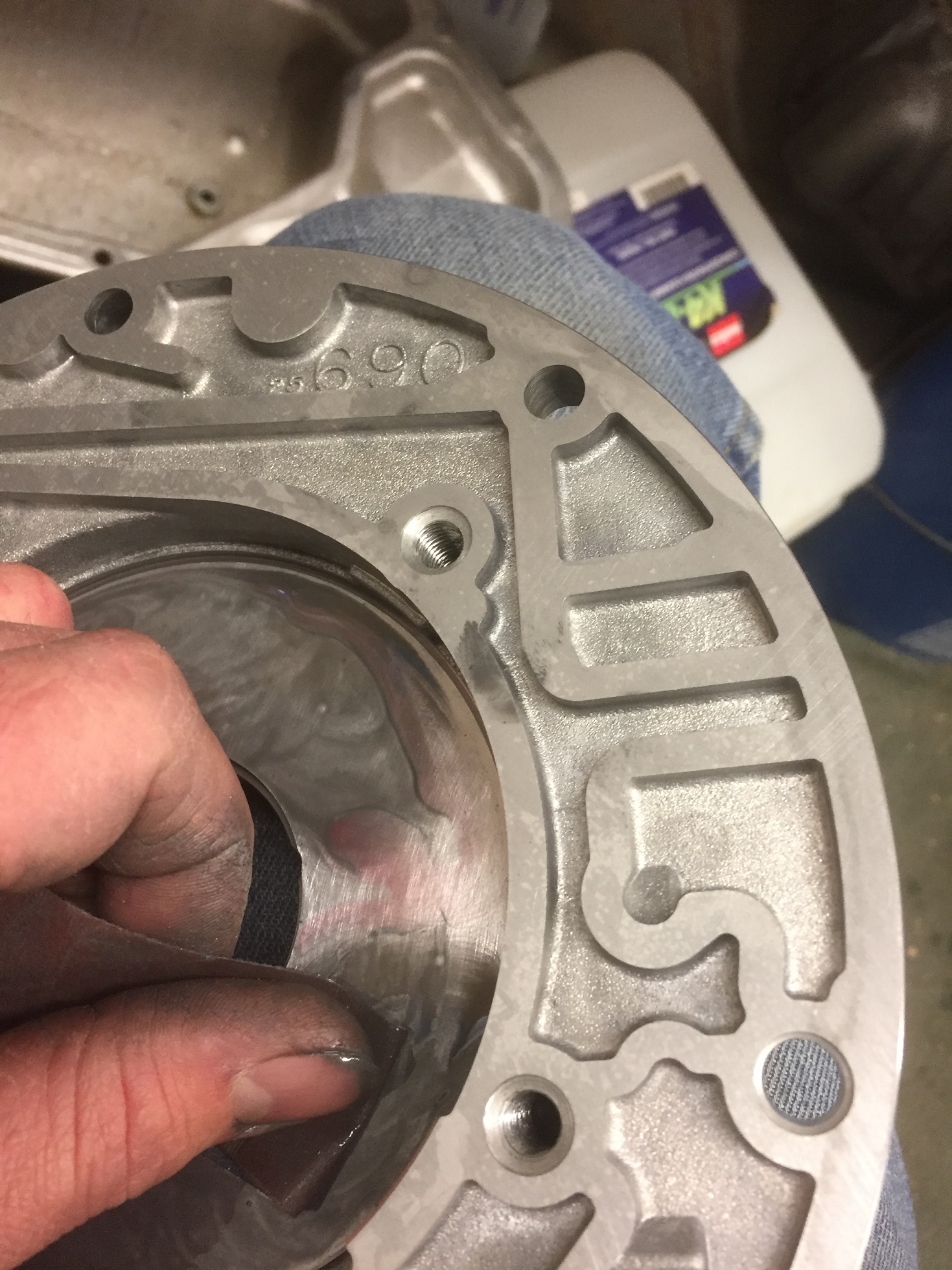
I have here), late castings are 082 body/088 cover and then the latest 690 body
which used the same 088 cover. Here's the differences:
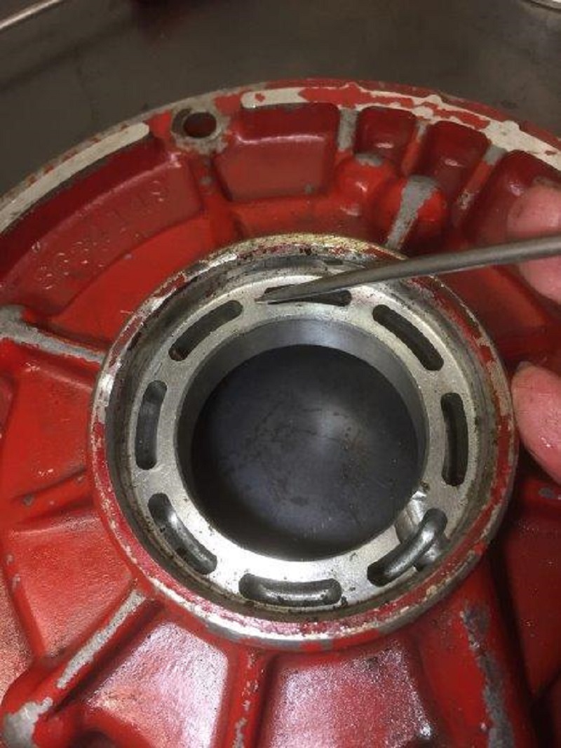
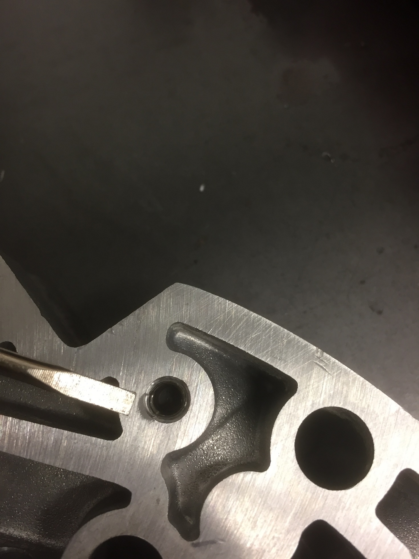
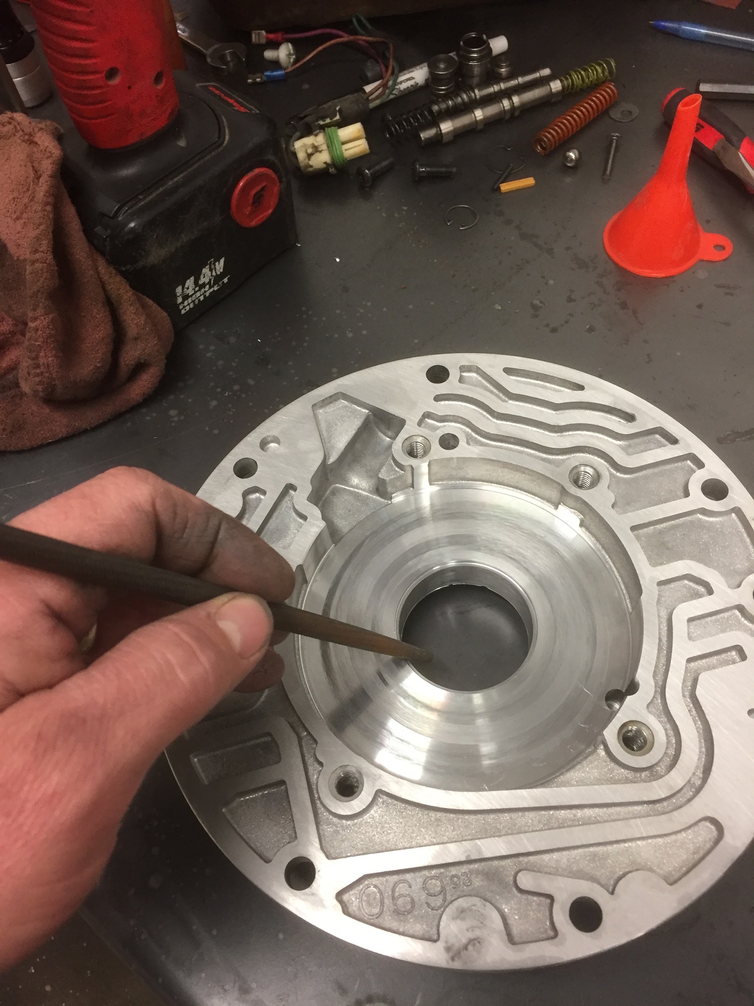
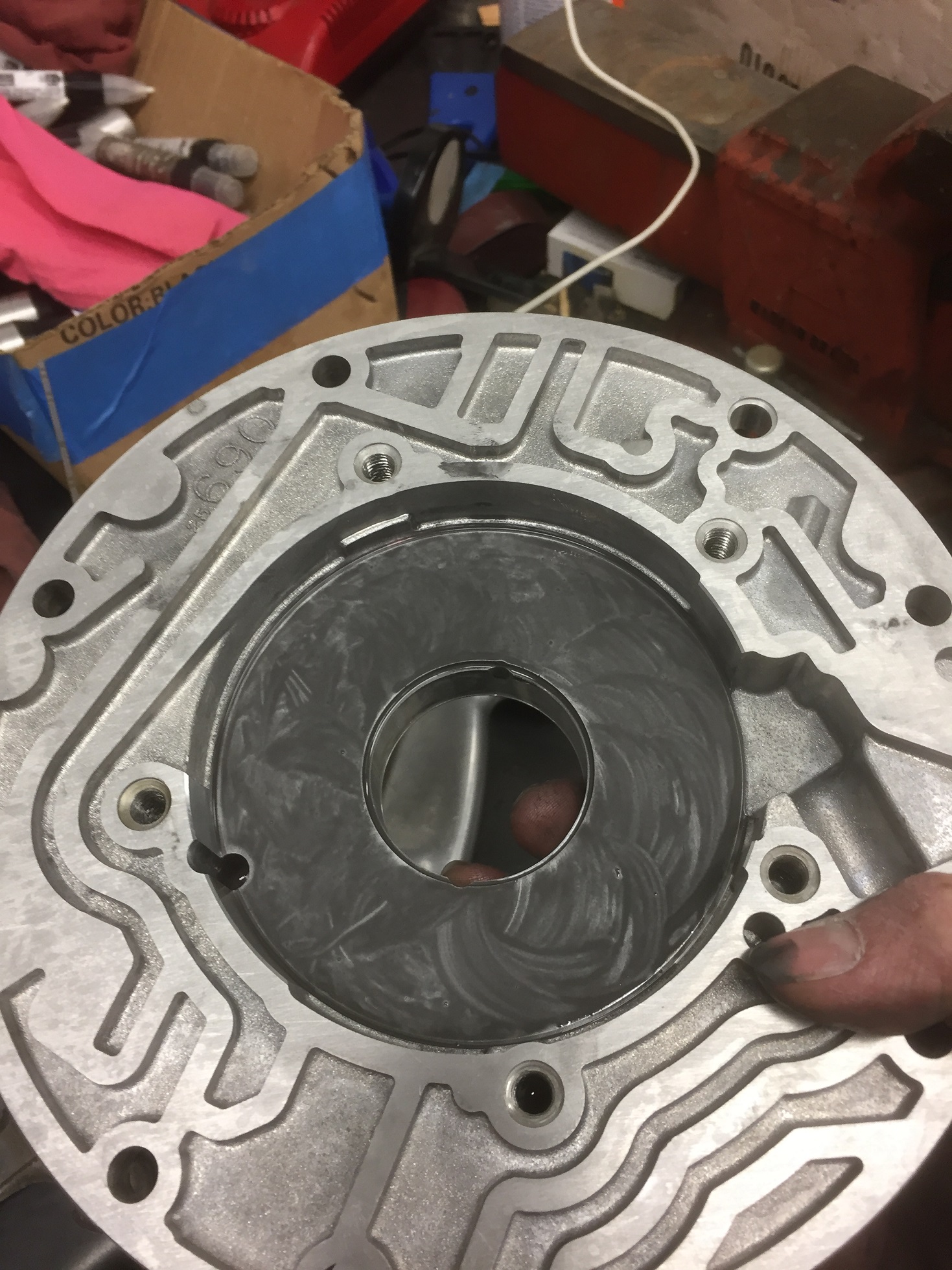
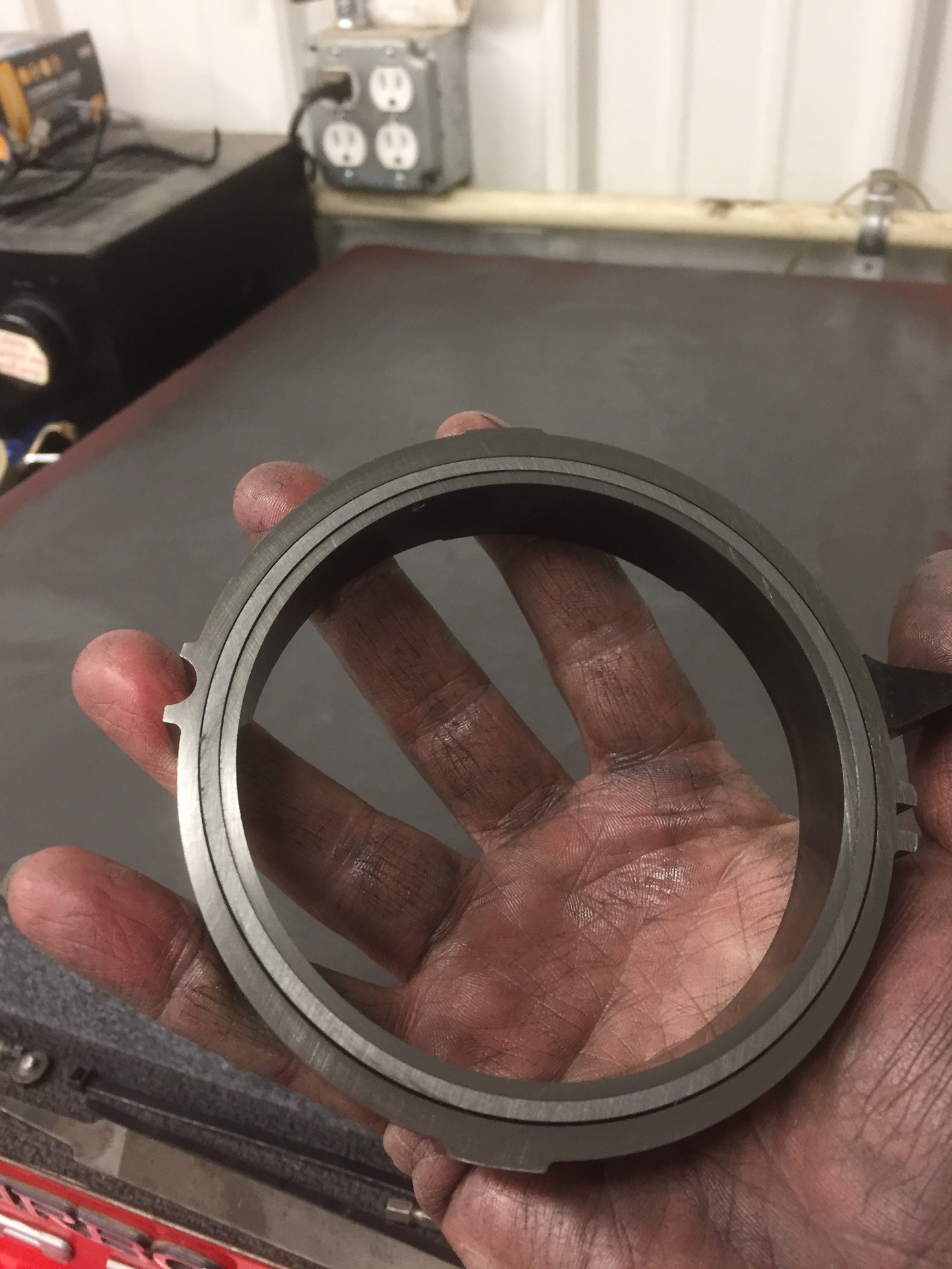
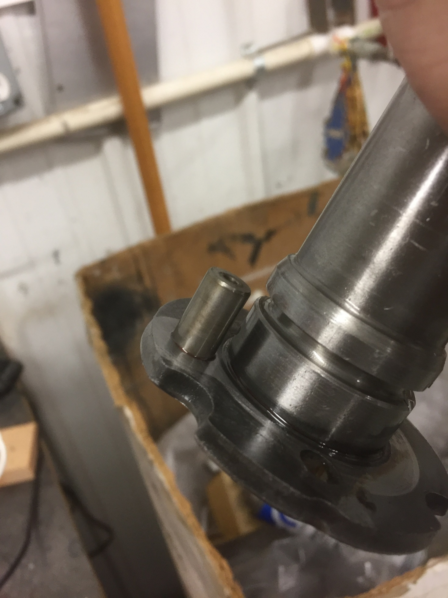
Early style
is the bottom housing in this picture. The cavity that the orange screwdriver is
stuck into is line pressure. Note how the early casting has the top land of the
pressure regulator valve open for line pressure to exert force on it and uses a
solid valve, and the late casting has the top of the valve area closed off. Now
note how the late pr valve has a hole in it, EDIT: crap, you can't see the hole
in this pic. Anyway, the late pr valve has a hole in it that goes from the area
of the 90 degree pick, up through the valve and out the top of the valve into
the now sealed off cavity. Still gets the same line pressure to the top of the
valve, just through a different route. There's a GM service bulletin on the
change, it was done to help isolate the land from pump pulsing in an effort to
reduce PR valve buzz. I HAVE read mixed impressions about it's effectiveness.
Some claim they won't use early pumps and some claim there's no practical
difference. You do, however, need to know about this for interchange reasons.
The "proper" way to do it is to use the 149/150 early combo as an assembly with
the solid PR valve and use the late 082 or 690 body with the late 088 cover with
the PR valve that has a hole through it. However, the only combo that absolutely
won't work is to somehow end up with an early solid PR valve in a late housing.
If you mix/match the parts it'll work as long as you have a pr valve with a hole
in it. However, it'll work the same as an early design with line pressure acting
directly on top of the valve and not through the hole.
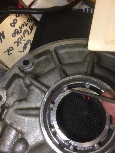
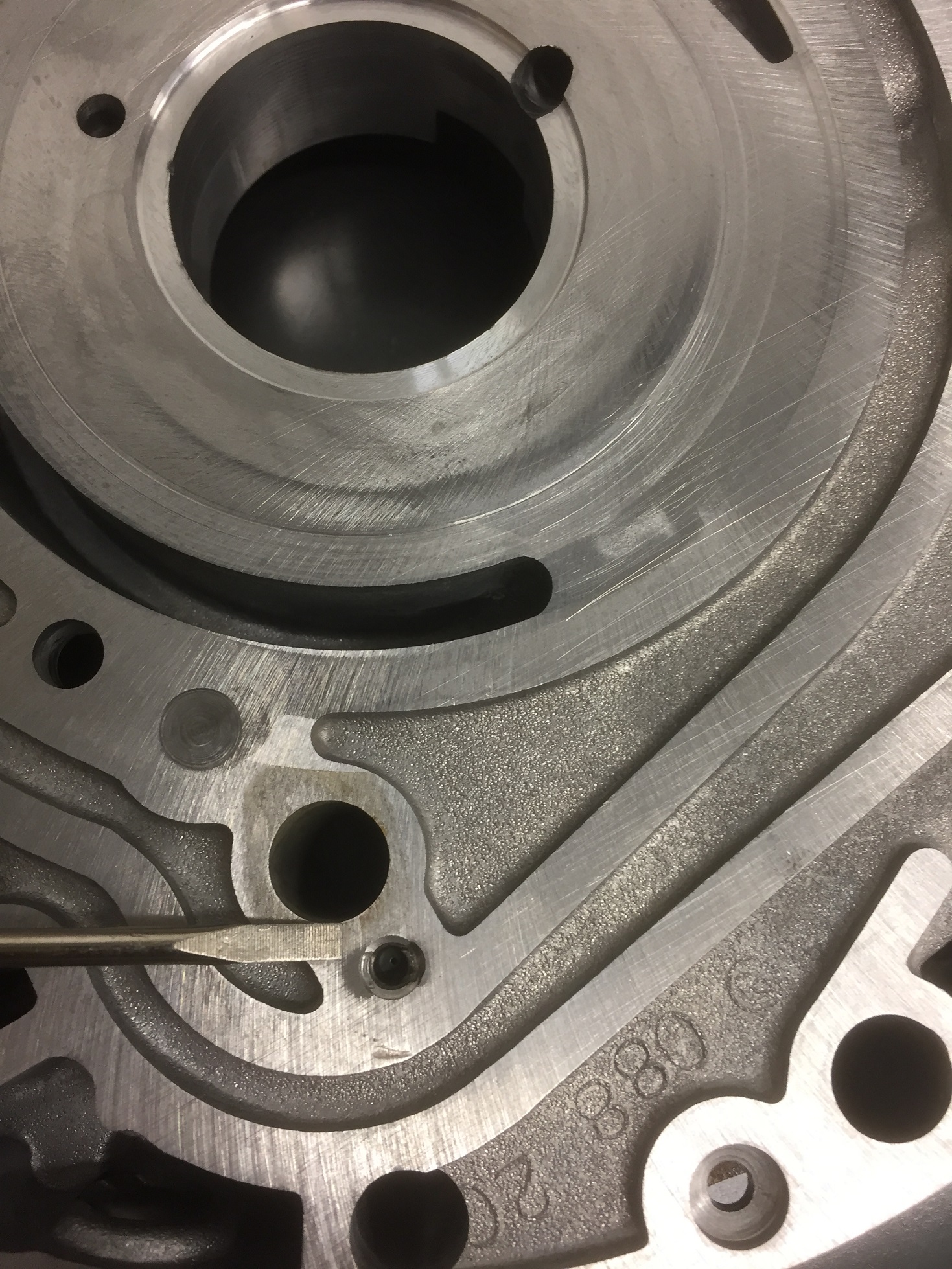
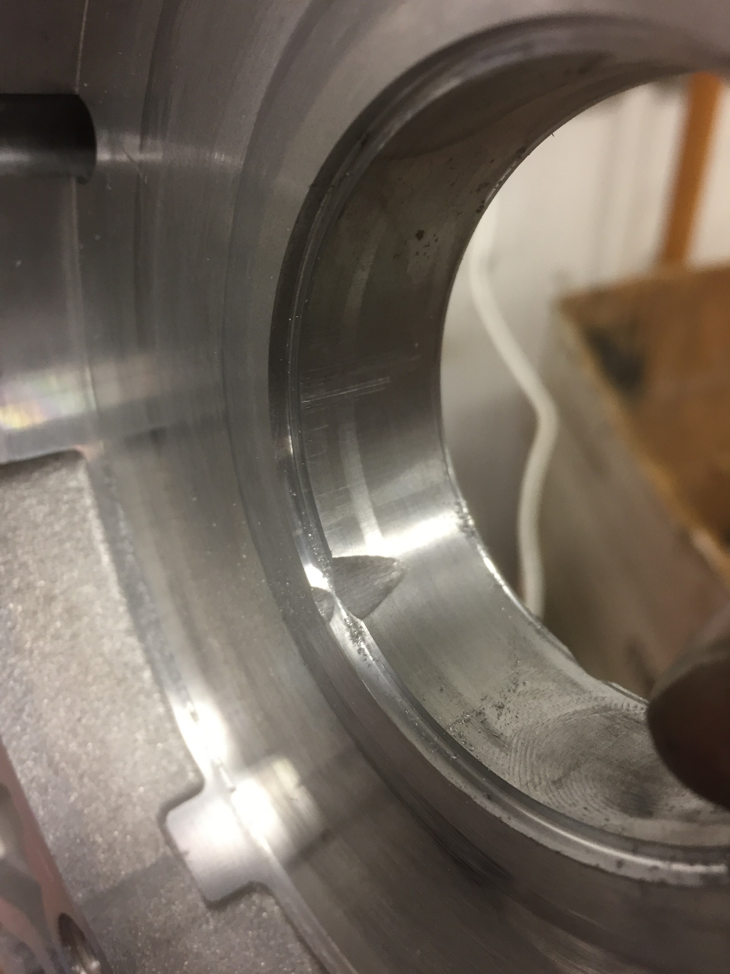
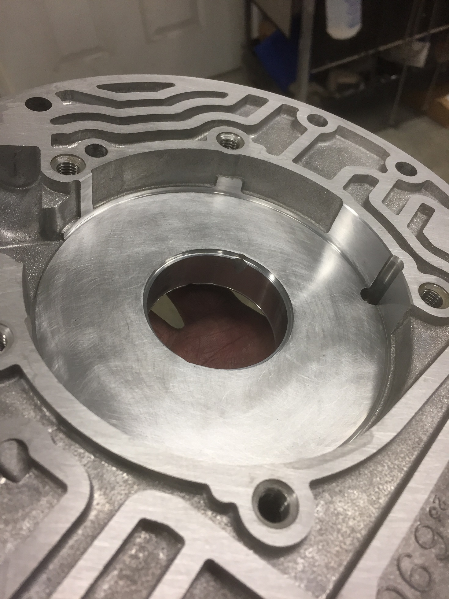
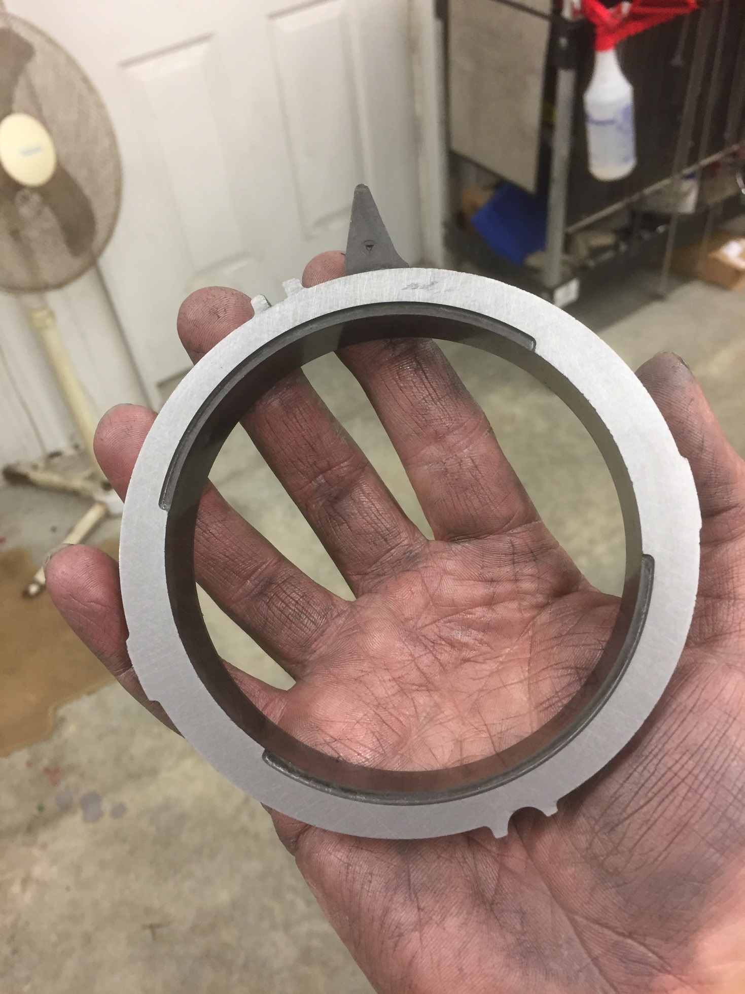
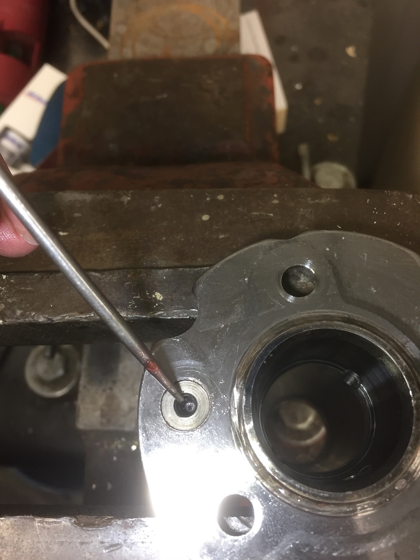
Next pic shows the early
and late pump bodies with the tools pointed at the same holes as the cover in
the previous pic. Note how the late casting was revised with a larger flat
machined area to fully isolate the valve tip from line pressure and forcing it
to go through the hole in the revised valve. If you use an early body with the
late cover it will allow line pressure to go around the newly sealed off cavity
and negate any gains from the design change. It WILL "work", however.
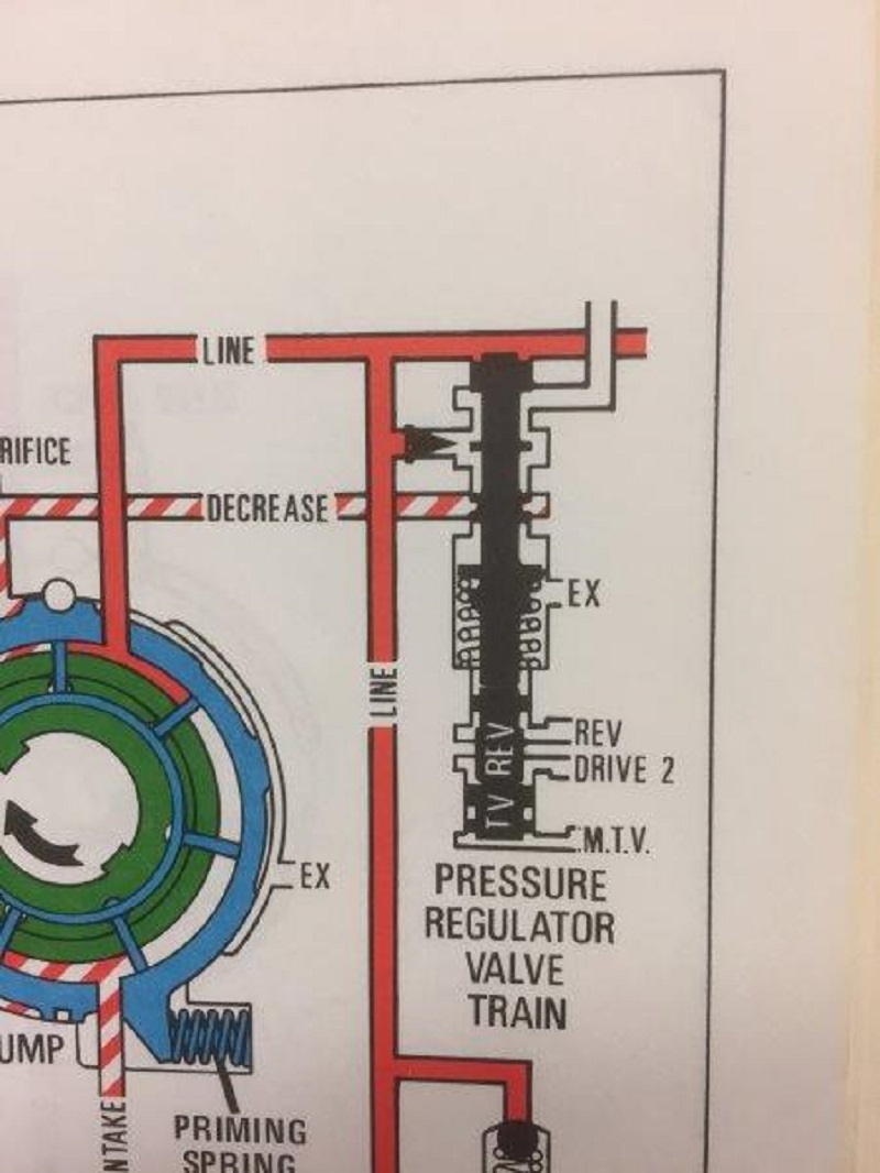
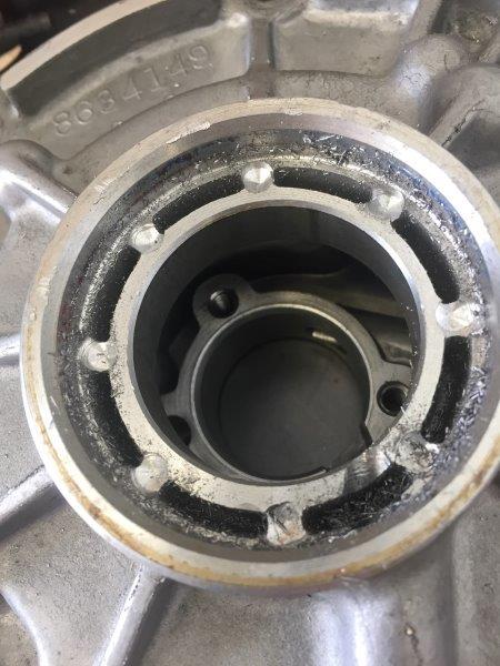
Next pic is
of the pr valve circuit from the manual. My manual only shows the early design,
not sure if a later revision bothers to show the late design?? Edit: It
doesn't.
Again, if
anyone has more detailed info or testimonial from using early vs late pump
castings, I'm all ears.
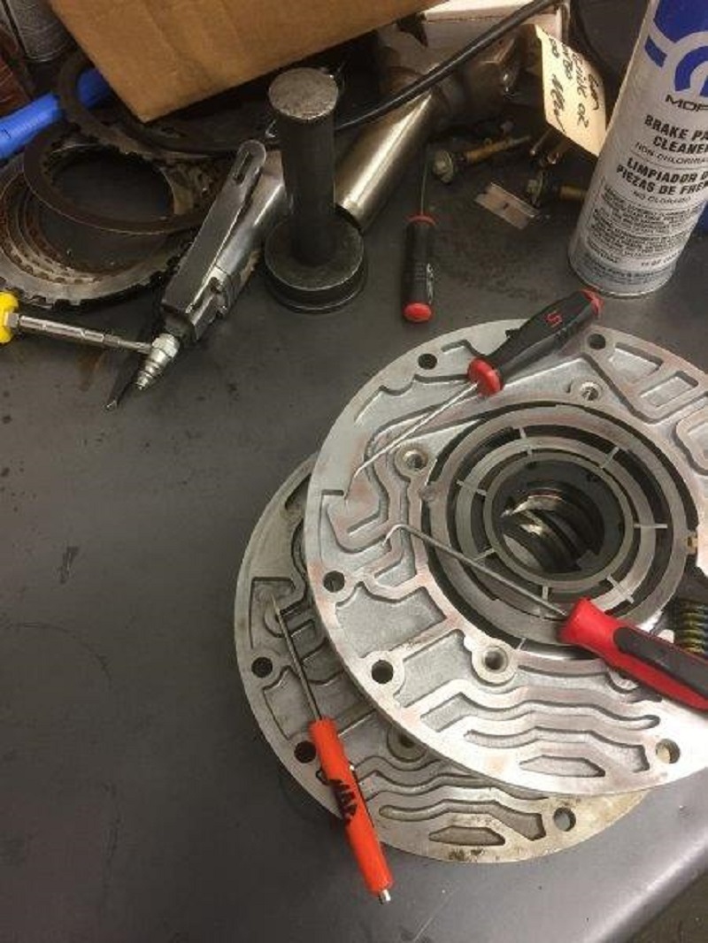
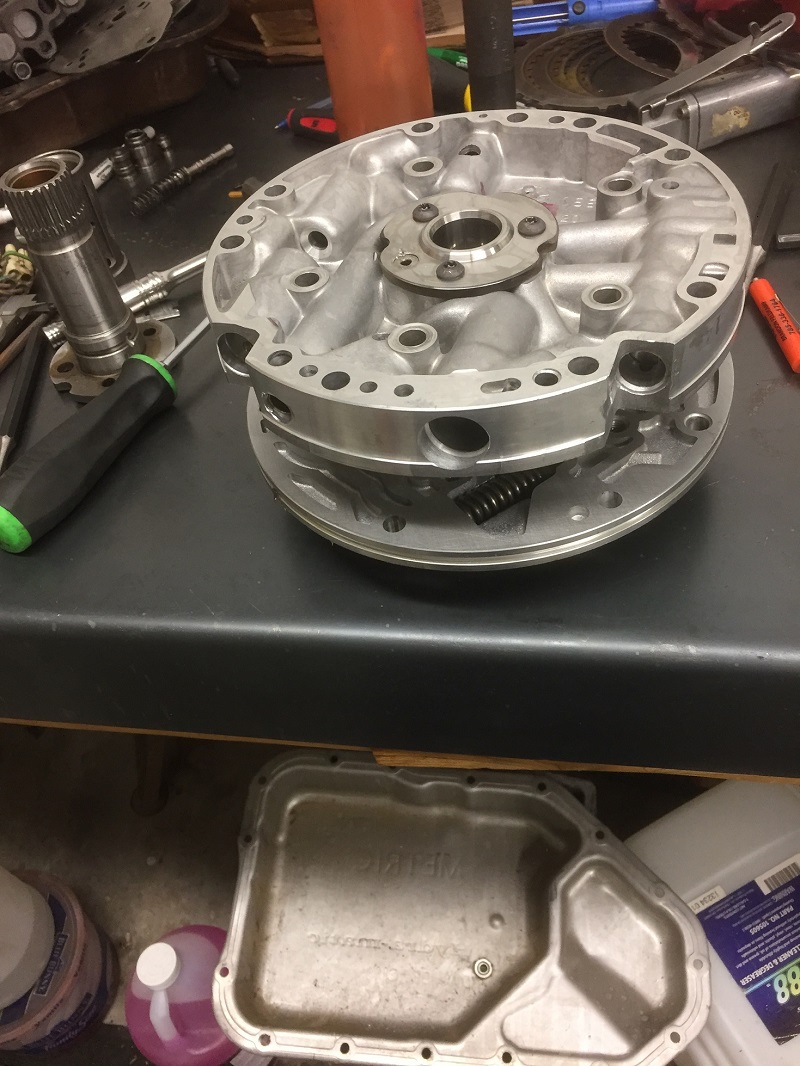
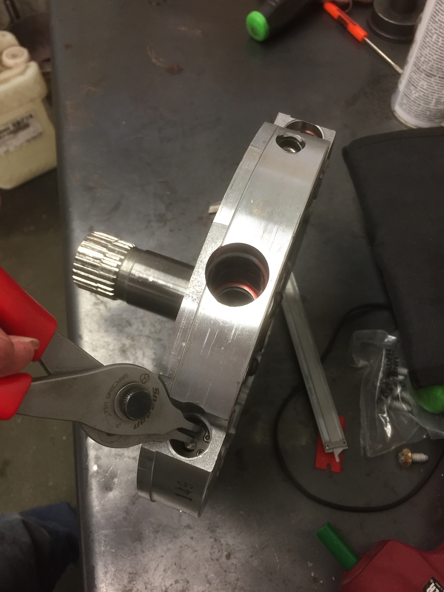
Teardown:
Remove the 5 bolts that hold the two halves together, set the stator side of the
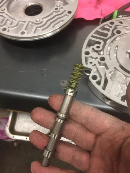
pump aside and start on the pump body. Remove the top ring, the rotor and vanes,
and rotor guide. Pry the spring(s) out from the slide with a rag over them to
keep them from flying off. For some reason I forgot to take pics of all of this
:red face: but i assume you have a manual of some sort if this is the first time
you've been in one of these anyway. Remove the slide, pivot pin and pay special
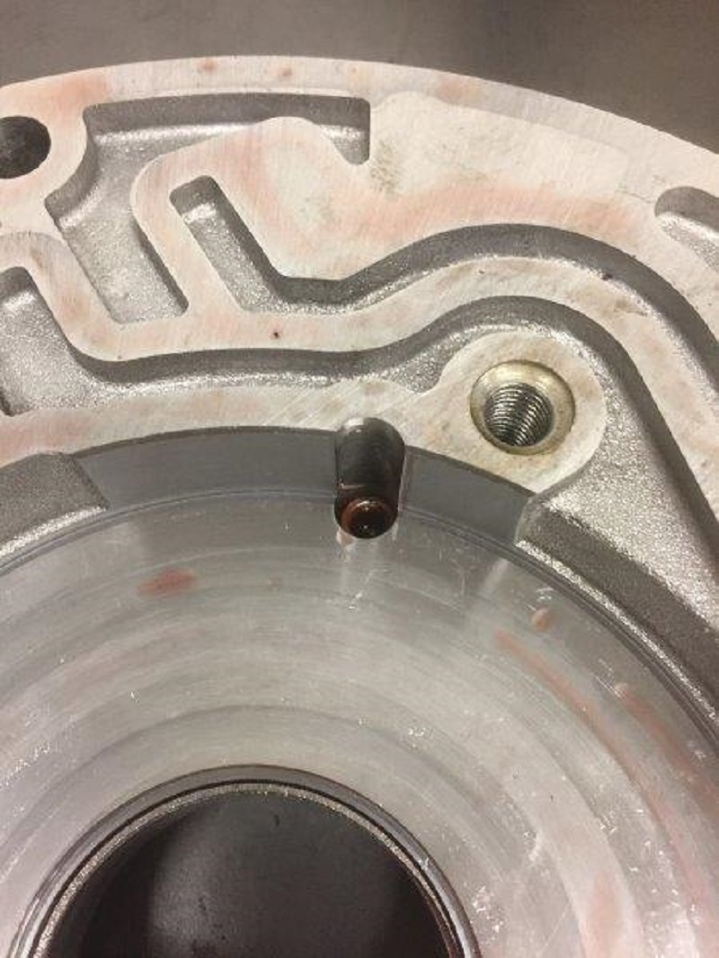
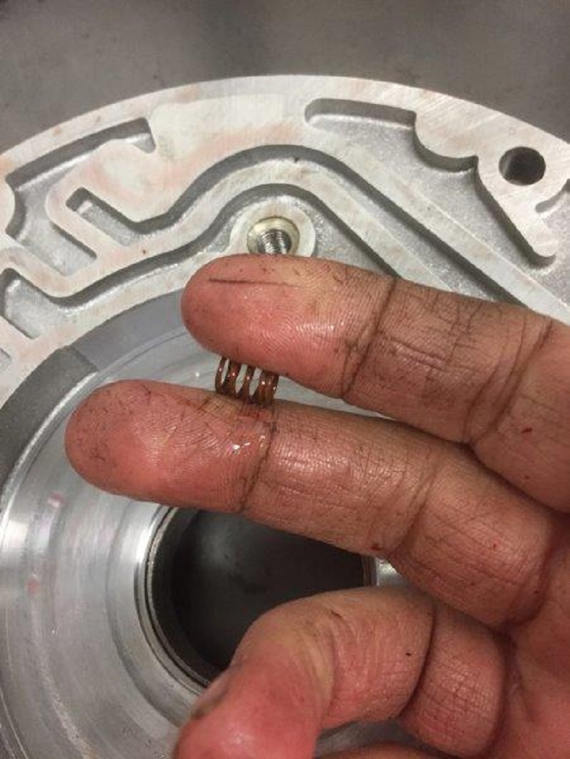
attention not to lose the little spring under the pivot pin.
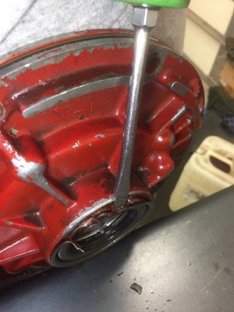
Now take a screwdriver
and hammer and pry out the old seal: (I'm using the red pump only because I've
already removed the bushing and seal from the one I'll be building).
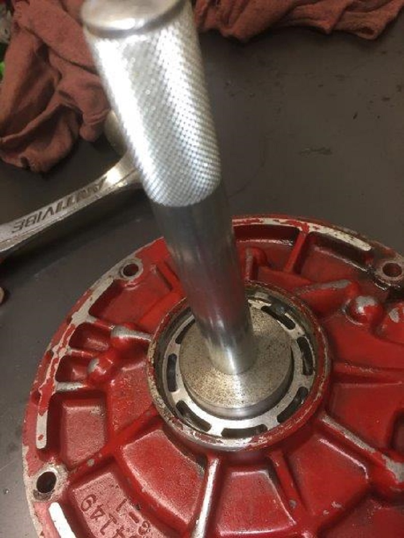
Using a bushing driver,
remove the bushing. If you have a 690 pump body, you will have to remove it by
driving it "inward" because the 690 pump body has a ridge in it to prevent the
bushing from walking out. You can remove this with a screwdriver or chisel
(carefully) but you'll want the proper driver to reinstall it anyway. Mine's
custom made just for this bushing, I haven't looked but I'm sure they are
commercially available.
Next two pics
will show the difference in seal area. 149 and 082 are identical here. 690 has
the aforementioned step as well as a bit more relief for seal drainback.
Bruce
from PTS was an avid believer that the earlier bodies needed to be milled out
here a bit to match the 690s profile for a drainback aide. I doubt it makes any
difference in reality but just for fun I'll include a pic of one of my
adventures doing the same thing in redneck fashion:
don't
recommend that "mod" I just inserted it for comic relief. Though I did put that
in a trans....
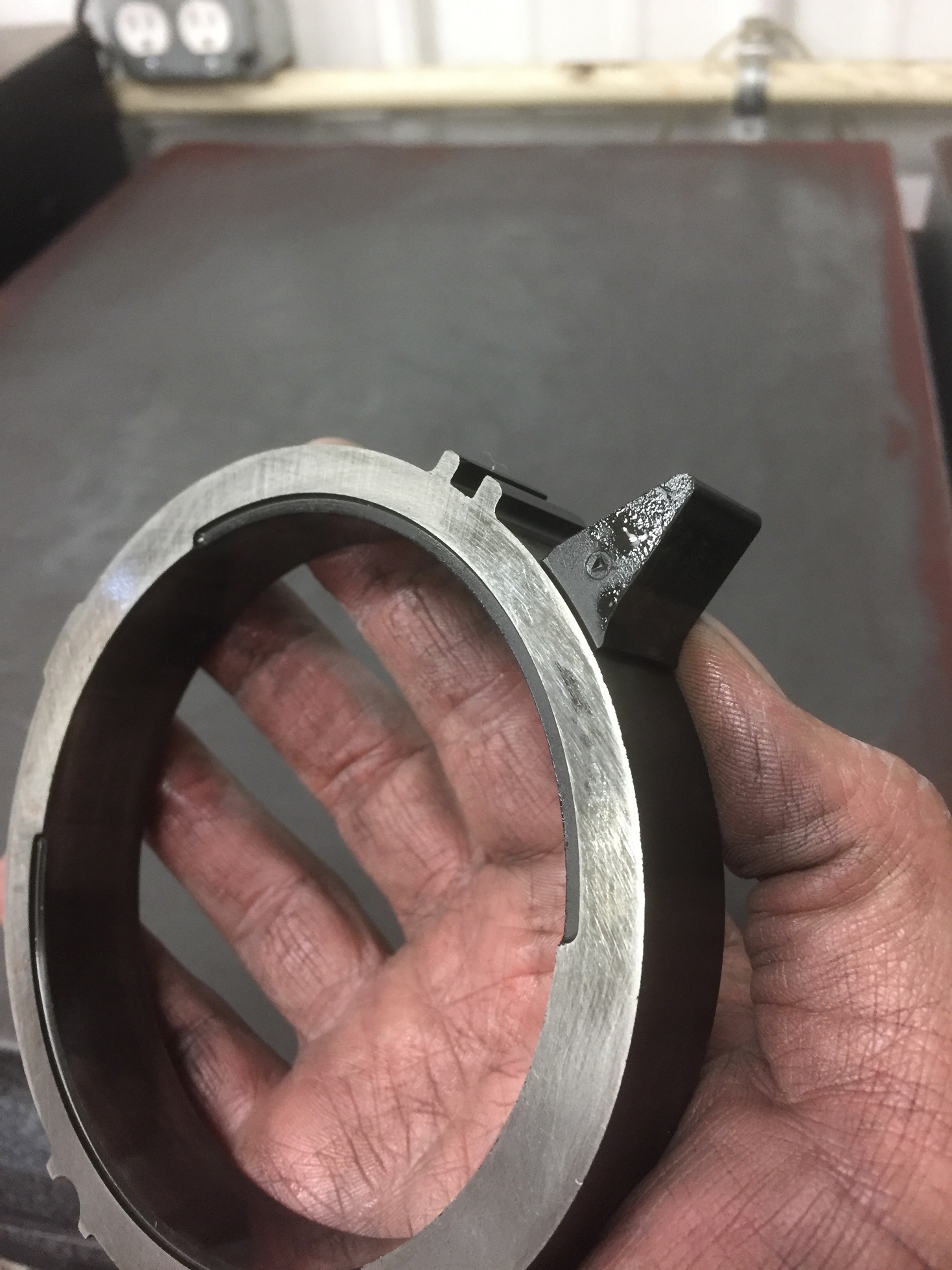
Inspect the
pump vanes where they contact the rings. If theres a visible notch in them,
replace them (same as 700 and cheap). You can reuse them if they're not worn.
Pic of an acceptable one vs a worn one (and they can be much worse than this):
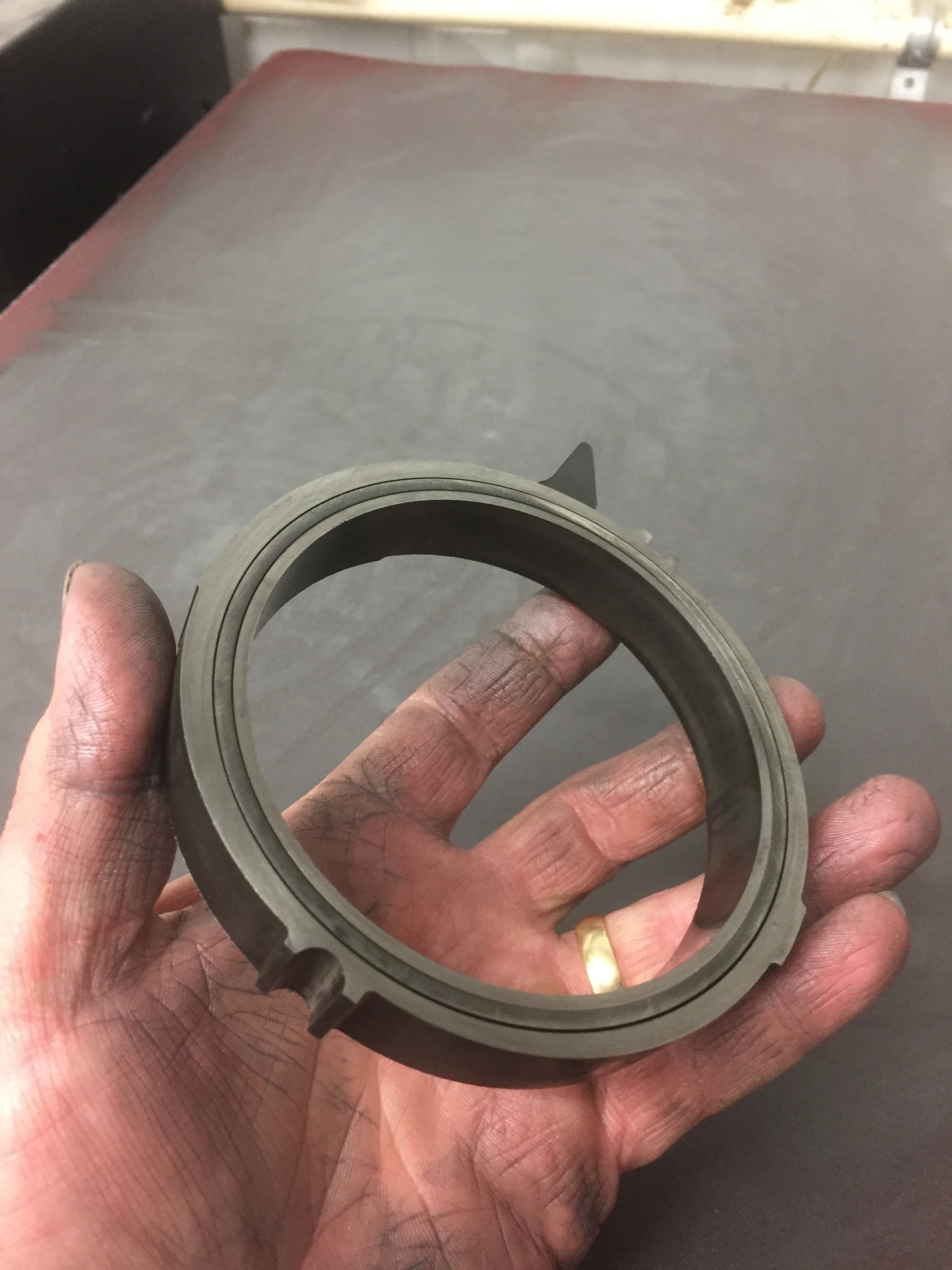
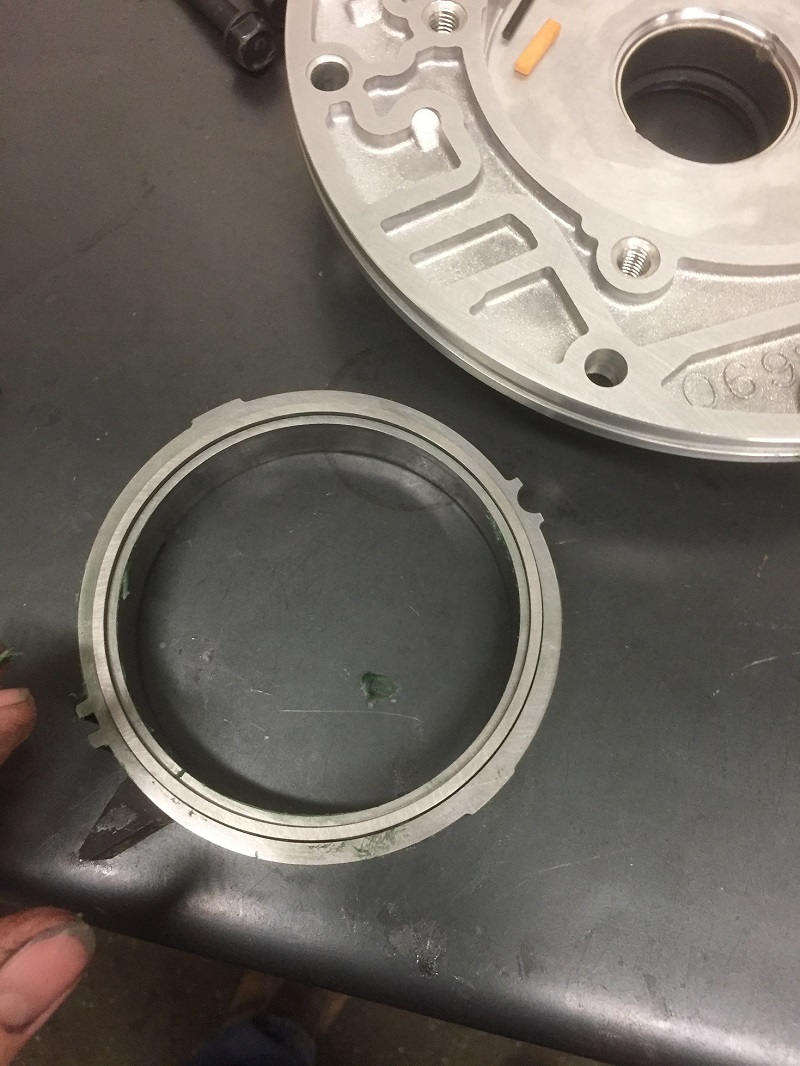
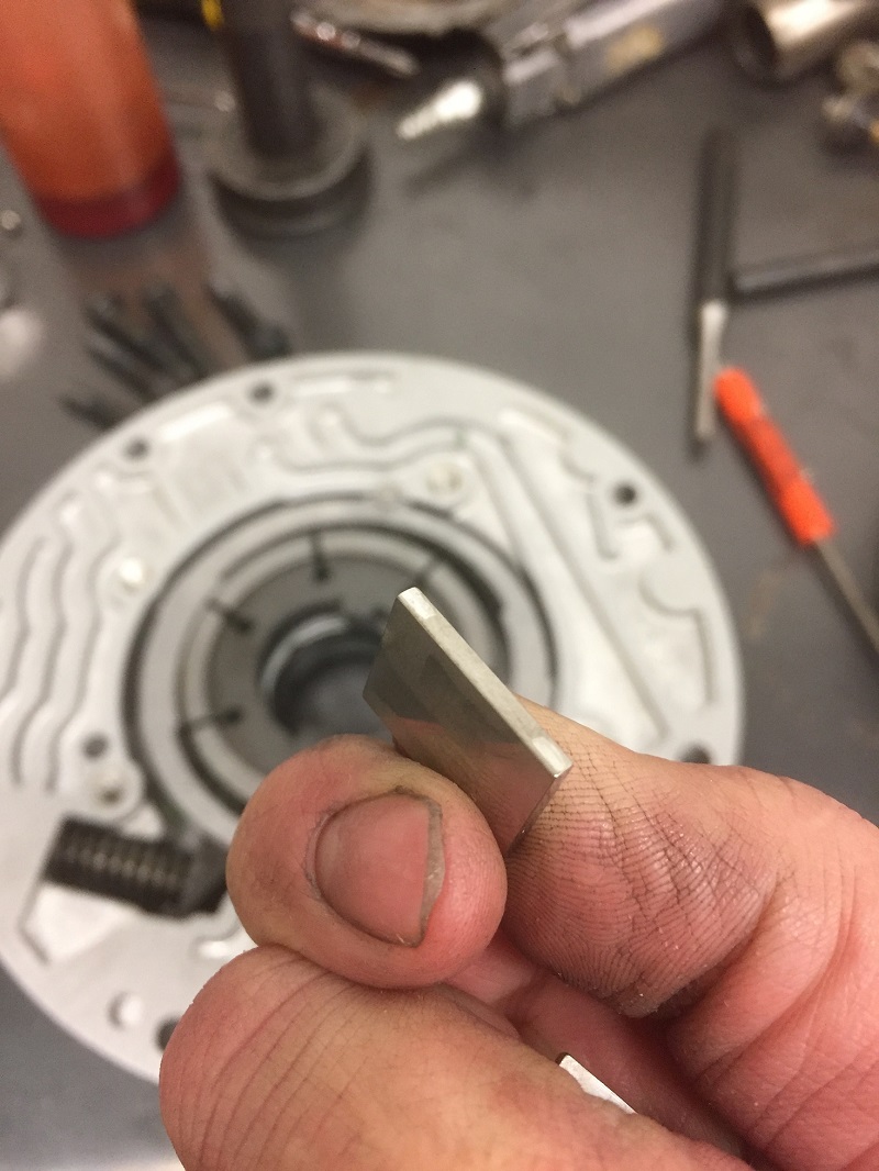
Now, take the original
pump rings, clamp them in a vise and snap them in half:
This is done to A:
illustrate how brittle they are and B: keep you from ever reusing them. We will
be replacing them later. (note: if its been apart it may have better rings in it
already and they may be harder to snap or impossible. Replace them anyway so you
know what you have. More on that later)
Plastic rotor guide:
Gently try to flex it. If it's not brittle it can be reused, but honestly,
they're like $1. Be sure you're getting a 7 vane guide when you purchase.
Obviously inspect the
rotor and slide for any cracks or obvious wear, on the rotor make sure you
inspect the tabs where the converter engages it. Now back to the pump cover
(stator side).
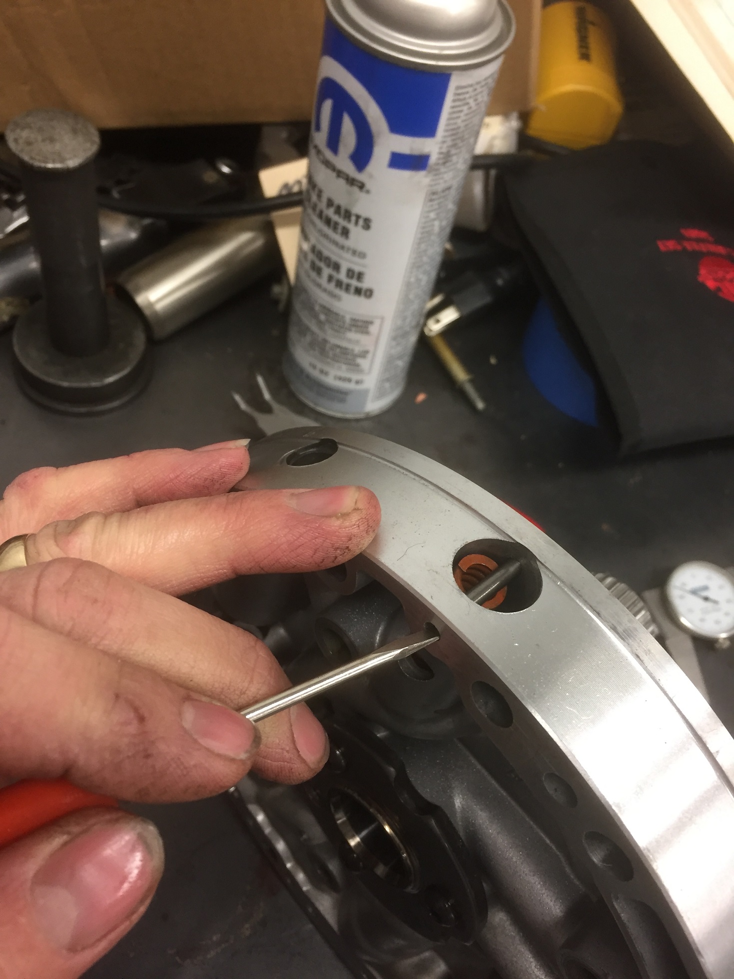
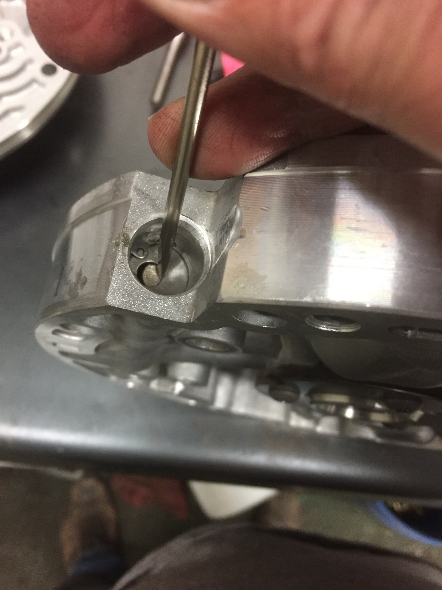
Take a snap
ring pliers and remove the PR valvetrain, starting with the boost valves. They
are spring loaded, so a couple gentle pushes on it usually gets them to pop out.
If they are stuck you can gently (and carefully) pry on the pr valve to help
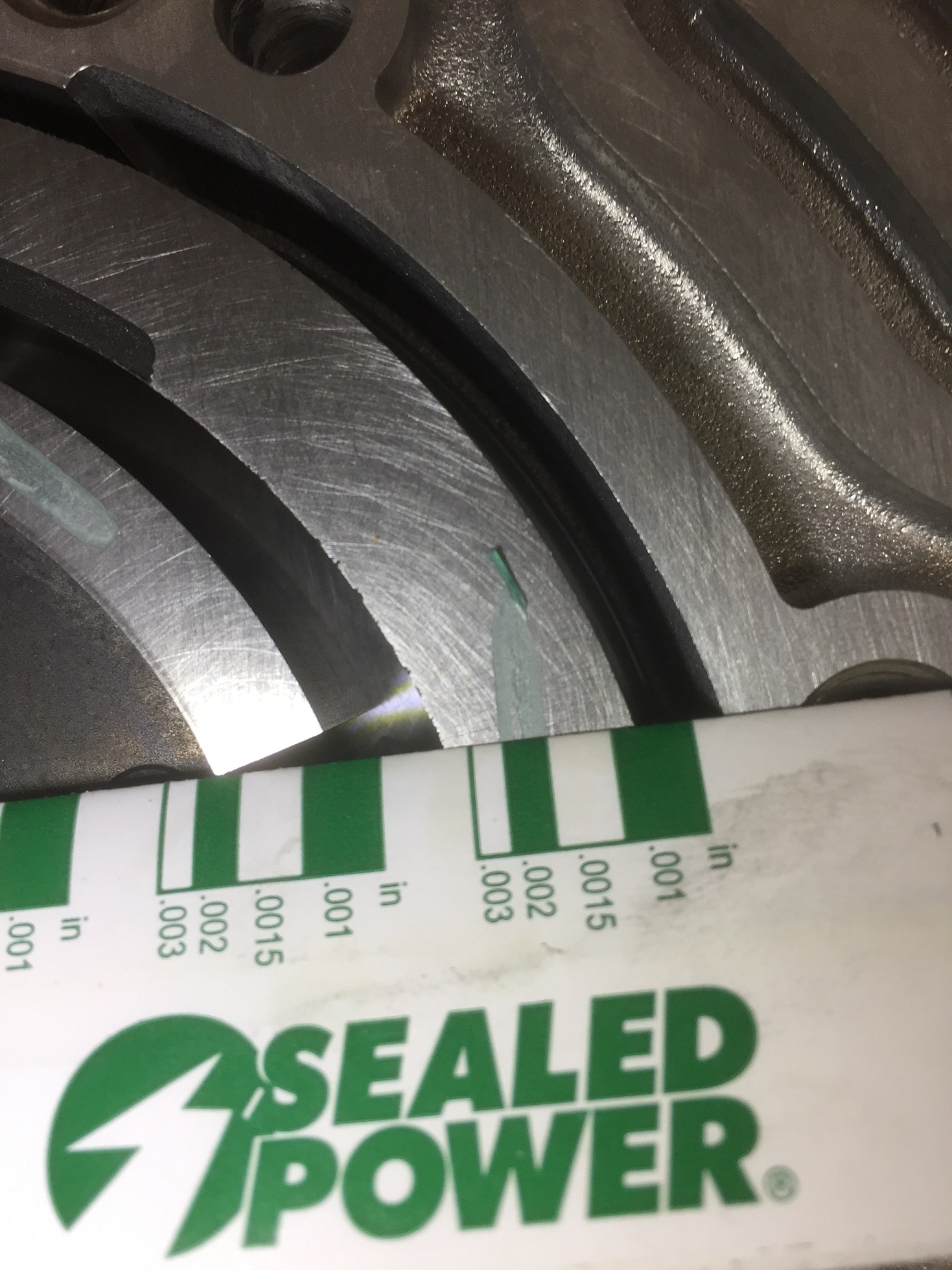
force them out. Just don't damage any valve lands or the machined surface of the
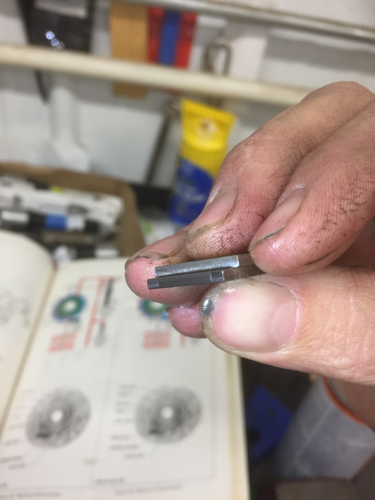
housing. I'm including pics of the lands you measure to determine the size of
the boost valves. This pump is out of a BRF core so it has factory .471/.265
valves. Note the hole in the PR valve as mentioned earlier.
Looking at
the next pic, the orange screwdriver is pointing to a land on the PR valve.
Sometimes this land gets modified with flat spots ground into it or ground
completely flush with the stem of the valve. The details of this get pretty
technical so i'll try to be concise but I doubt I succeed, because the actual
position of this valve under WOT will change depending on line pressure and
boost valve and spring combos. This land has the possibility (but not
guaranteed) to restrict and then cut off converter charge/cooler/lube flow under
heavy throttle, which preserves pump volume and limits converter charge
pressure. This modification is one of the big items falling under builder
preference. Transgo kits have you grind this land all the way off.
This may be beneficial in your 700r4 if you're towing a heavy load up a mountain
with an underpowered TBI 305 in your 91 chevy pickup. Most people reading
this, arent doing that. In fact, very few people with 700r4s are still
doing that 30 years after the fact. Understand that there's a difference
in usage between a truck towing a load with your foot heavy into the throttle
for long periods (and with a lower max pressure) and brief full throttle
acceleration in a car (with max pressures of 260+). Here's some math for
you to digest: The outer diameter of the land is .365" and the stem diamter is
.260". If you grind it perfectly flush, the area difference is about .0516
square inches, which is slightly bigger than the area of a 1/4" drilled hole.
A LOT of fluid can pass through that big of an opening at full boogie pressures
north of 260 PSI. Enough fluid, in fact, to create a serious converter
charge pressure issue if your transmission cooler circuit doesn't flow well
enough to deal with it all. There's a large number of aftermarket
radiators, trans coolers and fittings on the market that can cause a back
pressure issue that will overload the engine thrust bearing in this scenario.
Personally I'll never send one out the door with that land ground completely
off, but there may be some merit to grinding SOME material off of that land.
Once you get to max line pressure, the blowoff spring and ball are going to
exhaust some fluid anyway and letting it go through the lube circuit instead of
the blowoff circuit could be beneficial. GM eventually came to this
conclusion as well, as they had a revised valve in the 1993 model year 700r4
(last year for 700 and only in certain models) that had a flat spot cut into
this land. GM part number 8684048 is the valve in question. Long
since discontinued, if anyone has one i'd appreciate you measuring the flat in
the valve just to satisfy my curiosity. So what should you, the home
builder, do with this valve land? That's the million dollar question and
every builder will likely give you a different answer. I can tell you that
as of this writing (and re-writing), every one I've ever sent out the door had
an unmodified PR valve. Unmodified valves are drying up, however.
Superior makes an "upgraded" PR valve, i ordered one, side by side with the OEM
valve there's a bunch of small changes that I don't blindly trust, as of this
writing I can't recommend using it. If I ever get around to testing it (or
any other PR valve mods) I'll update this section (don't hold your breath). In
rare cases the top land of the valve may have a flat ground on it. It's a
transgo "fix" for the wrong pr valve/pump casting mismatch. If the top land has
been touched, definitely replace the valve with one that has an unmodified top
land and double check your pump casting/PR valve style combination as mentioned
in the first post. 700r4 valvetrain is identical and I also believe the Sonnax
reamer and oversized pr valve from the 700 can be used if the bore is worn or
you're that desperate for an unmodified valve. Be warned the increased valve
diameter of the reamed valve setup will alter the force applied by line pressure
on the top land and can affect your pressure rise. Someone correct me if I got
any of this wrong. I'm never too old to learn.
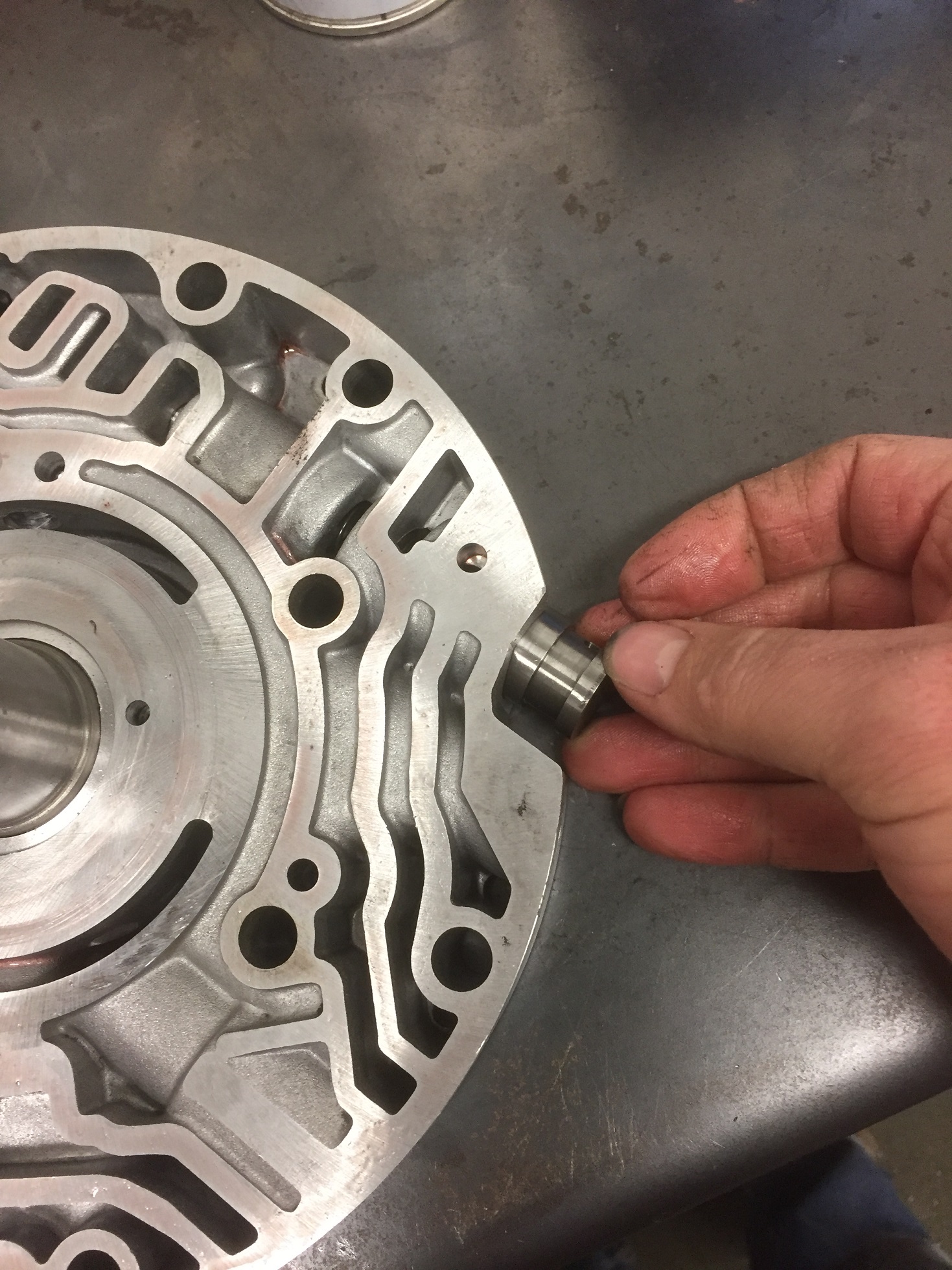
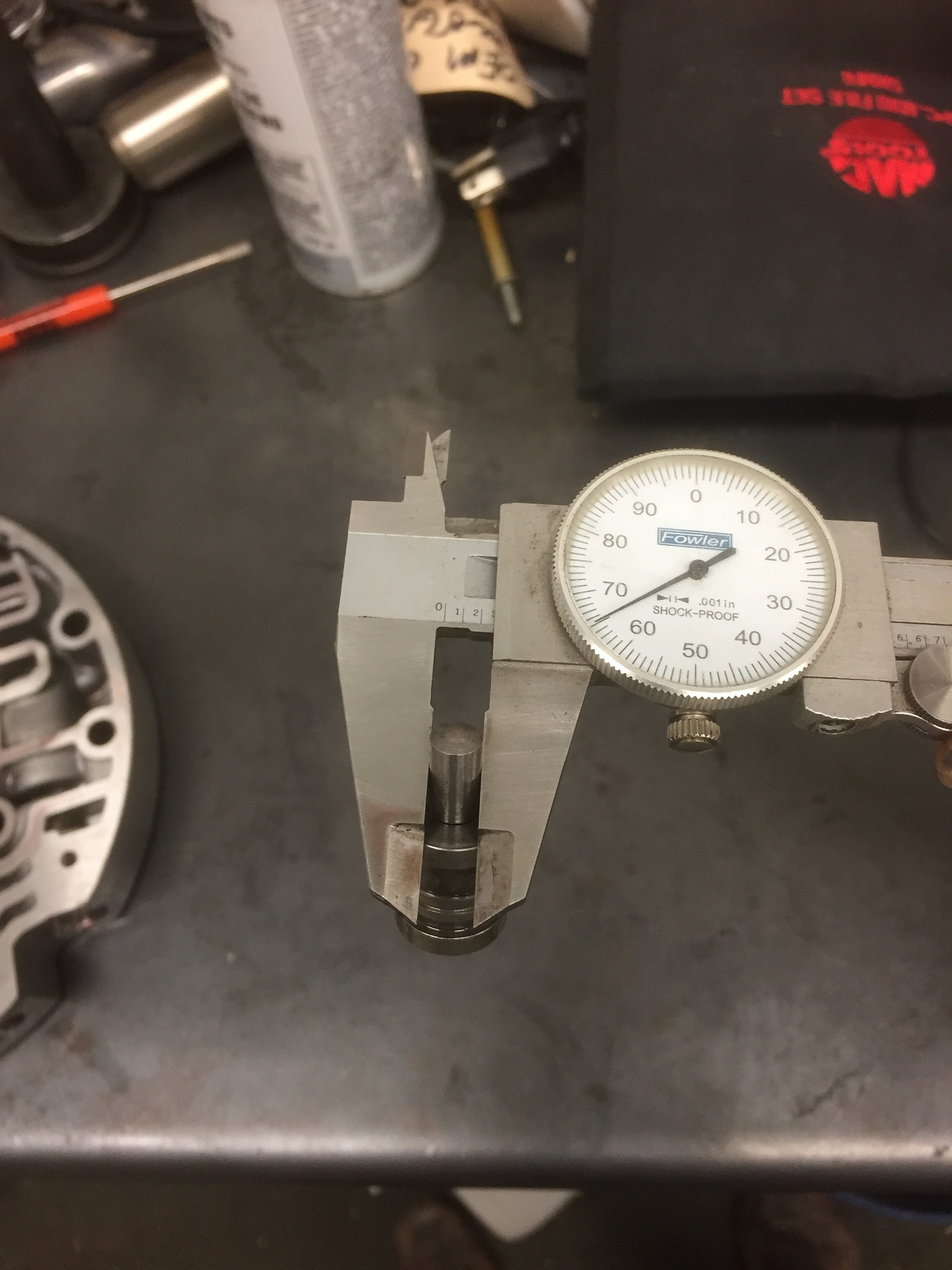
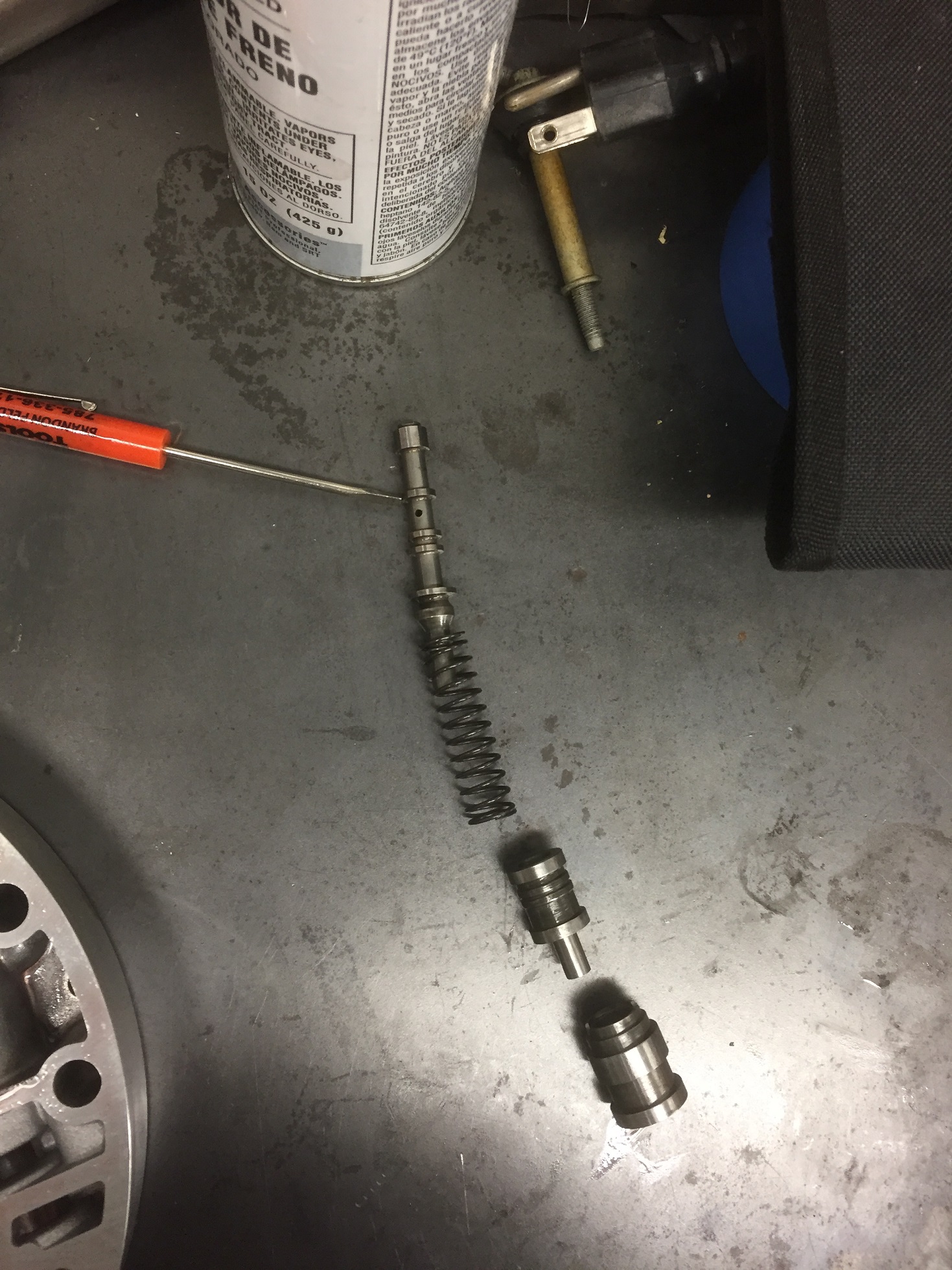
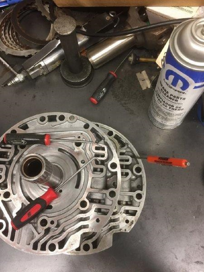
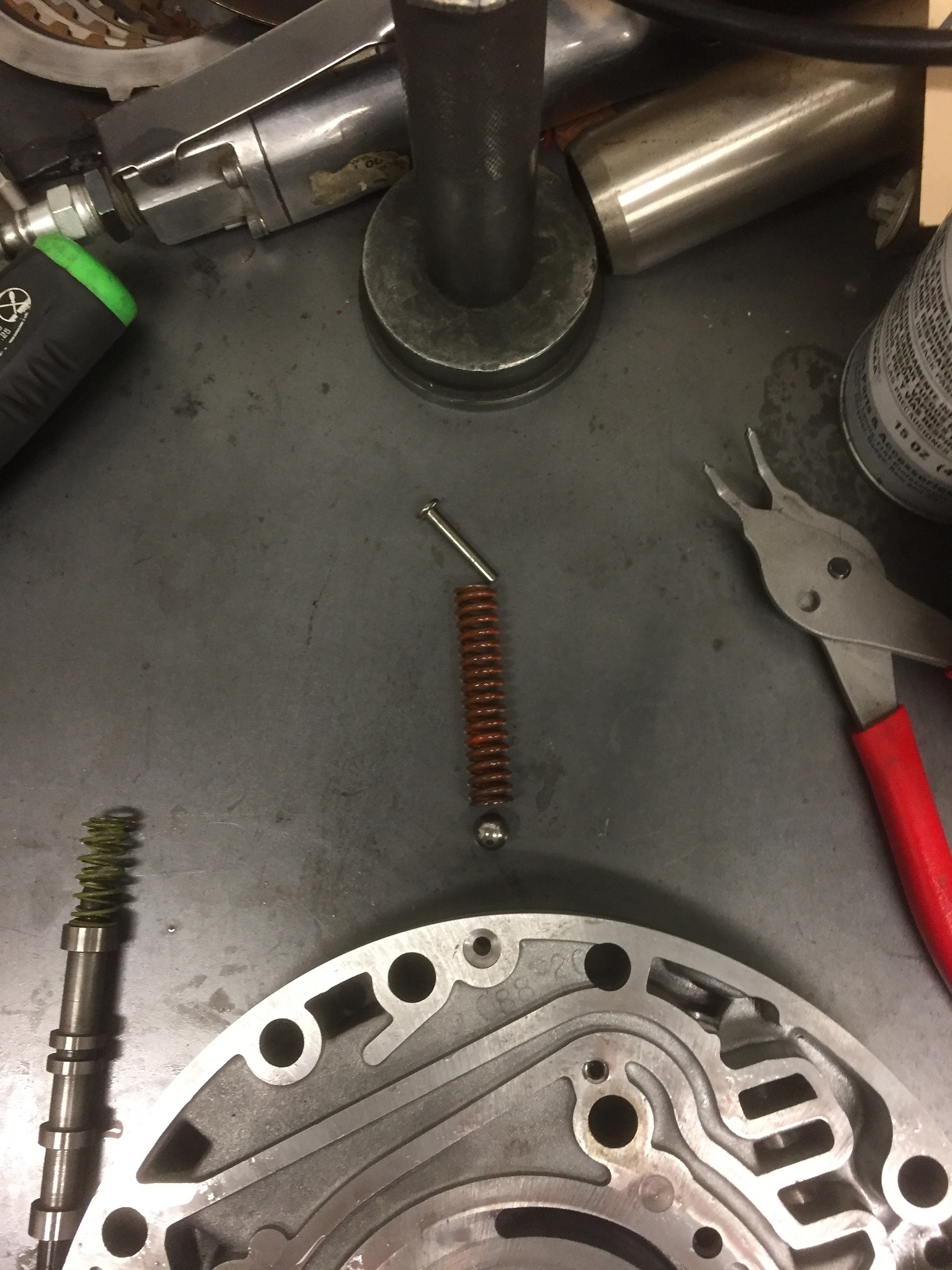
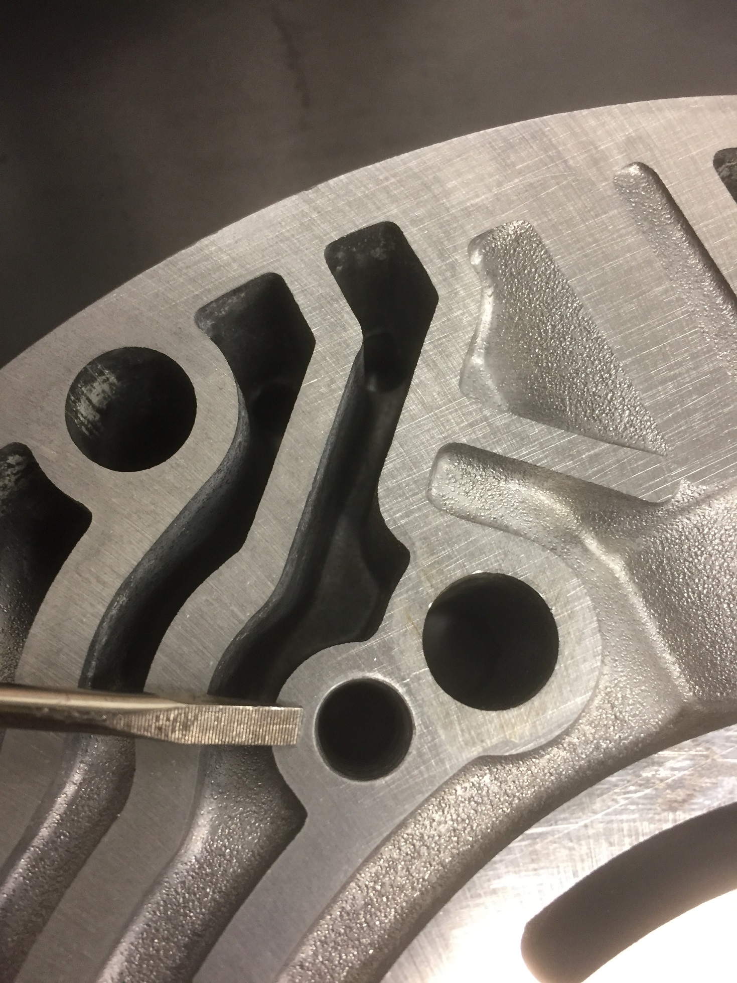
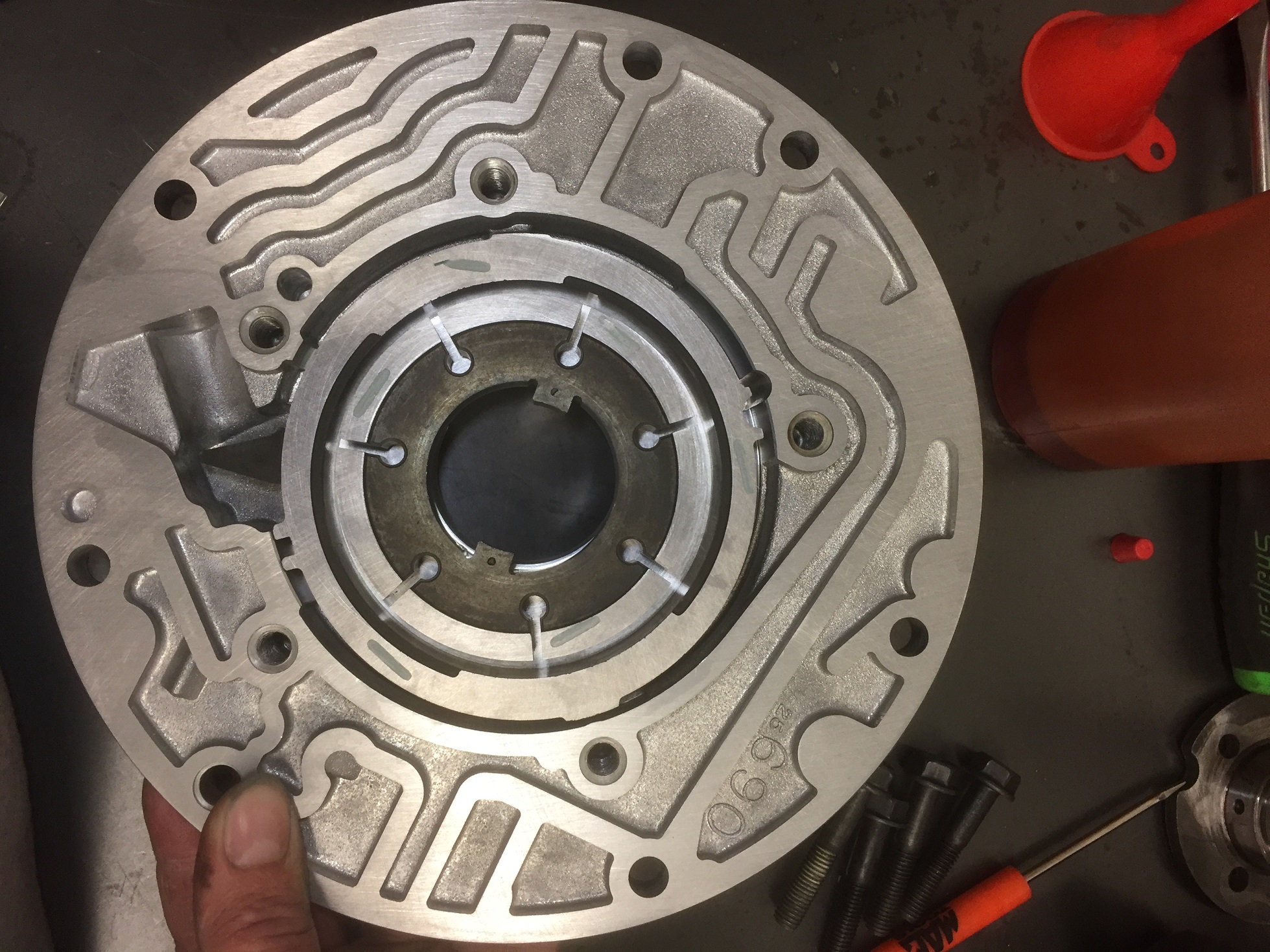
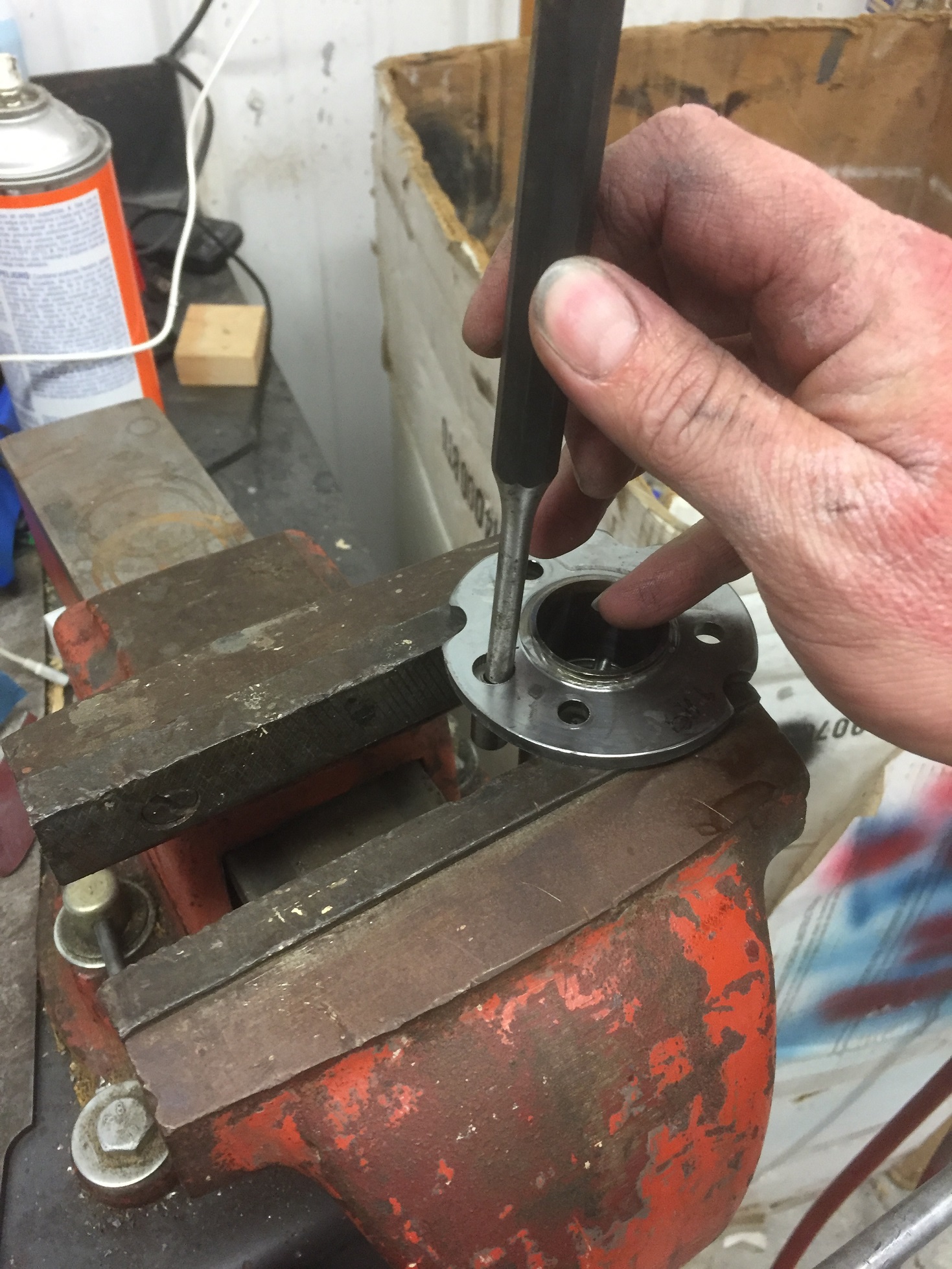
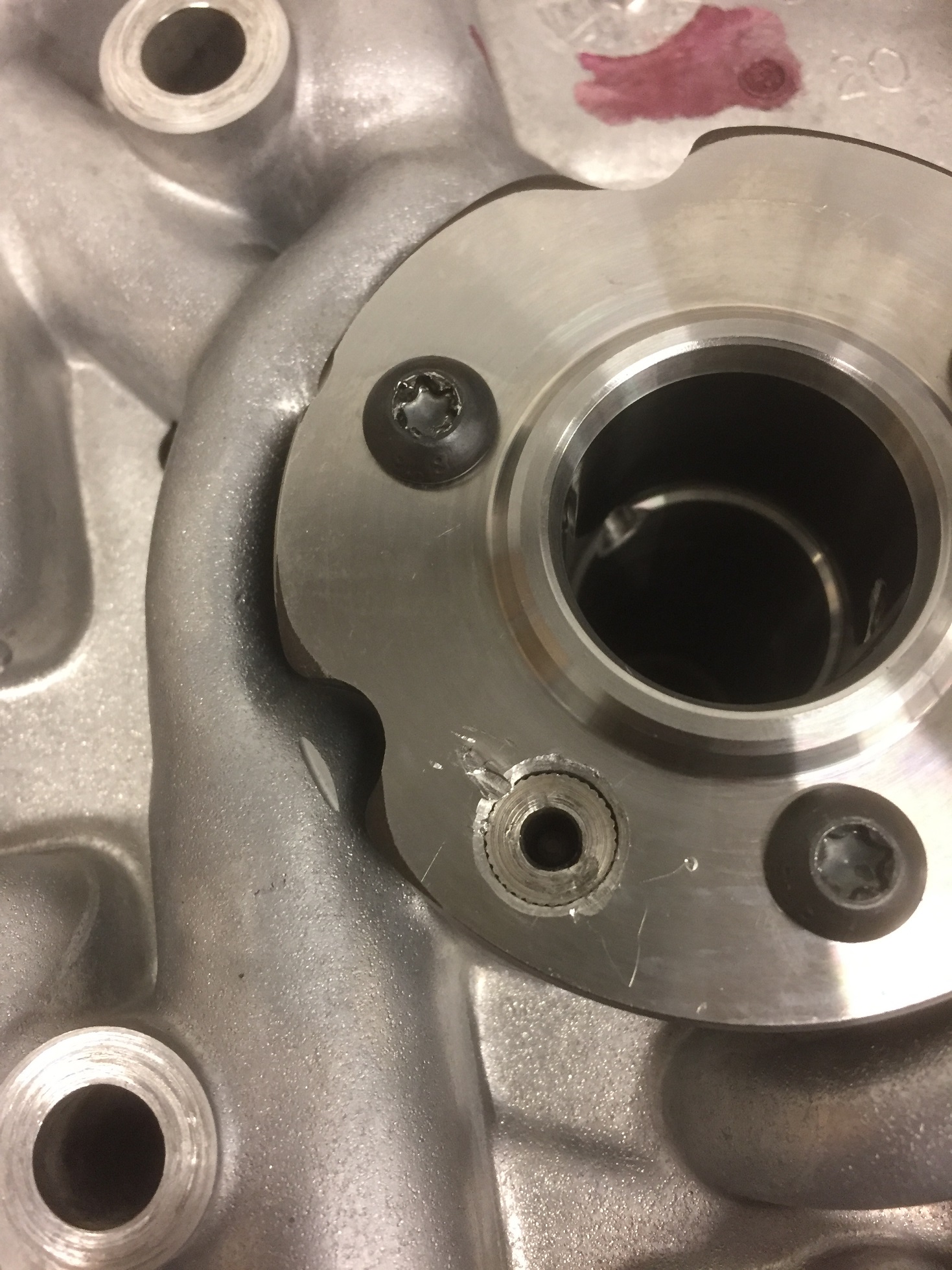
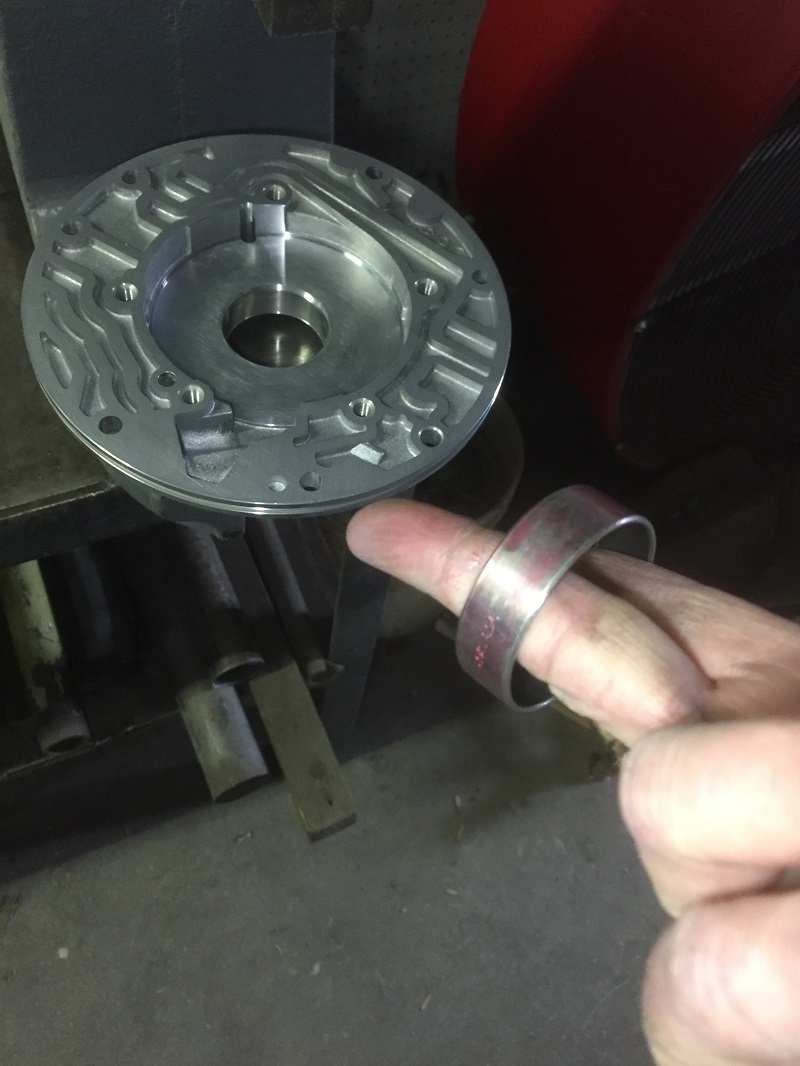
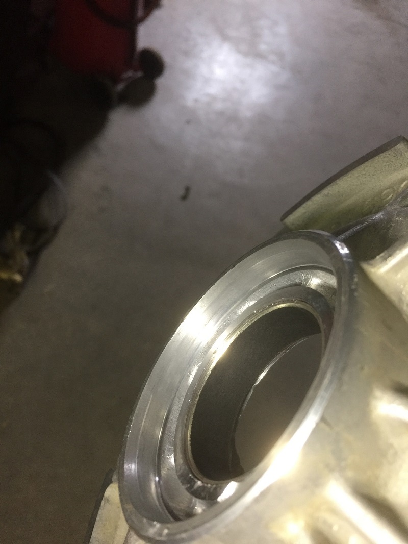
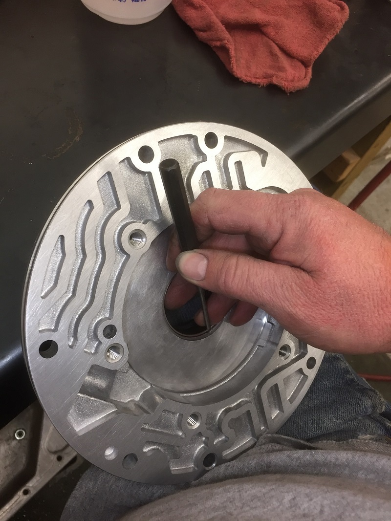
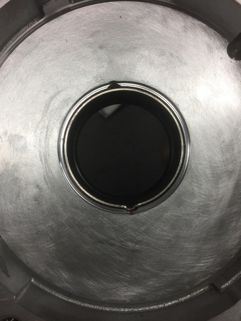
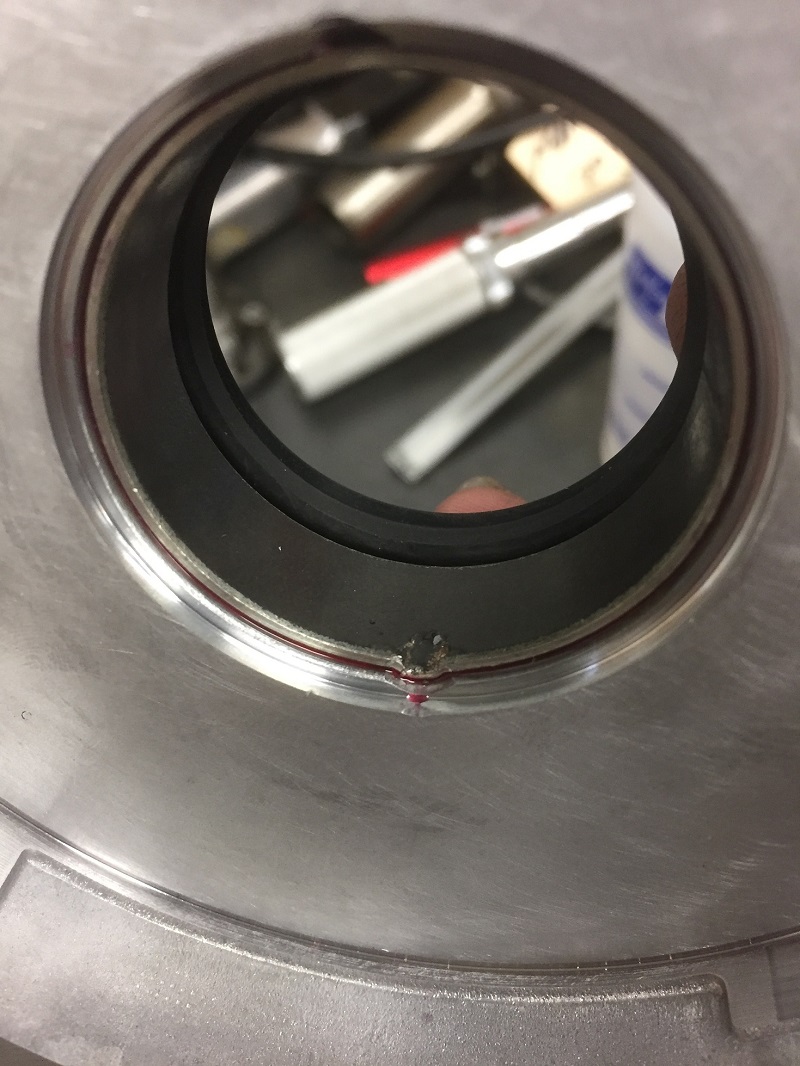
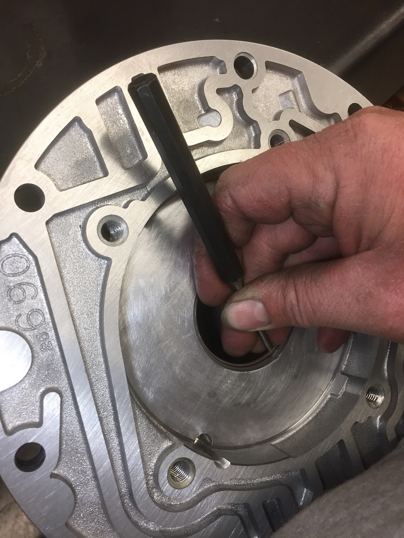
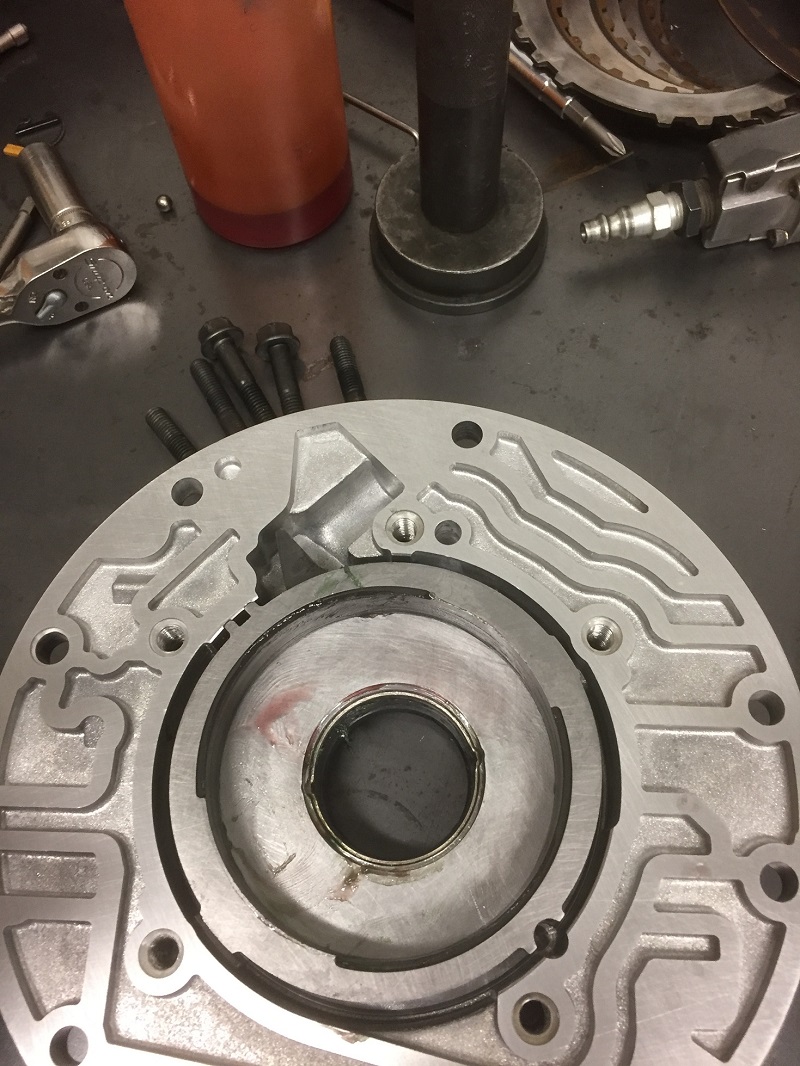
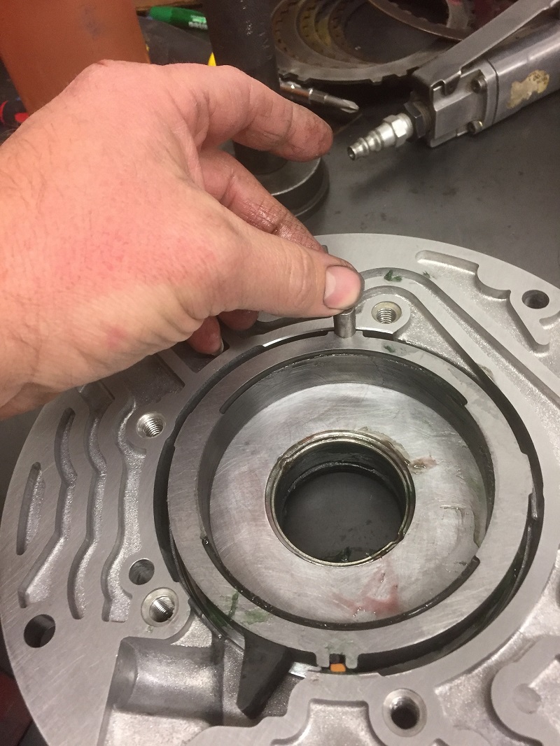
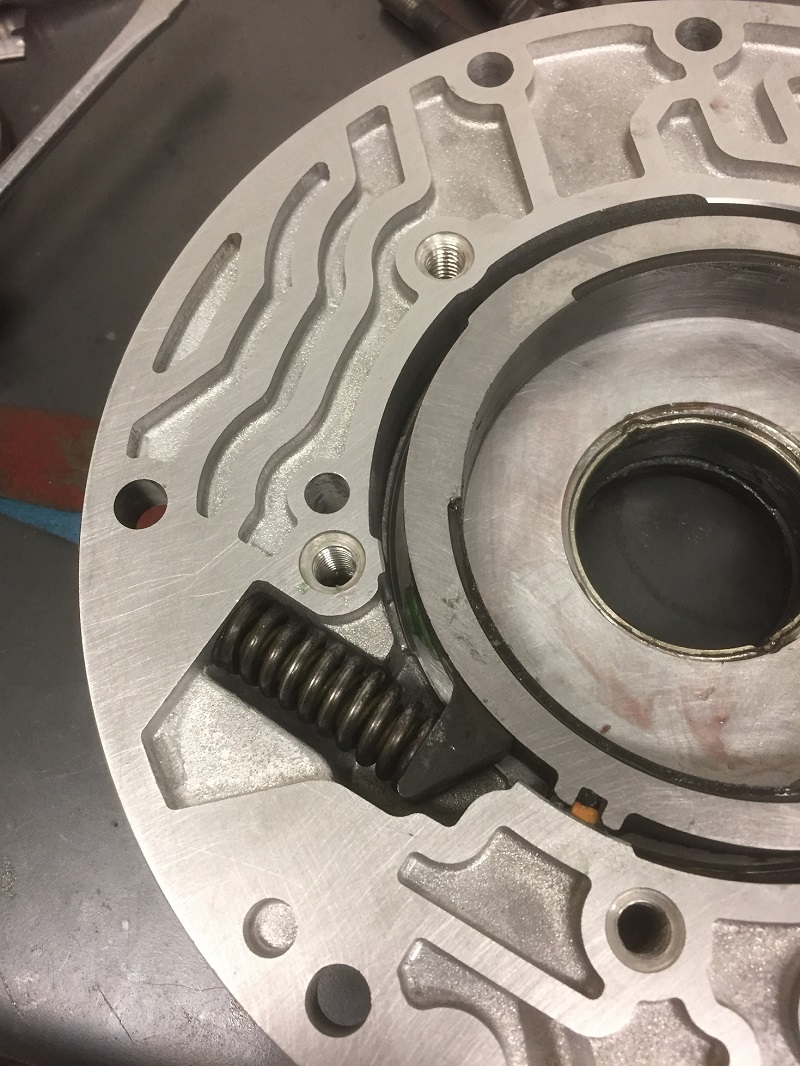
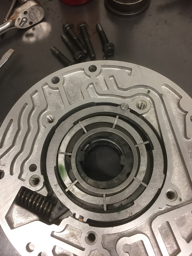
Remove the lockup valvetrain as shown. Then remove the pump relief spring pin, spring, and ball. It's a stiff spring so it's a good idea to cover it with a rag when you remove the pin. If there's a filter o-ring still in the housing, carefully pry it out without scratching the bore. If the bore is gouged from a previous filter change, now is a good time to smooth it out with fine sandpaper.
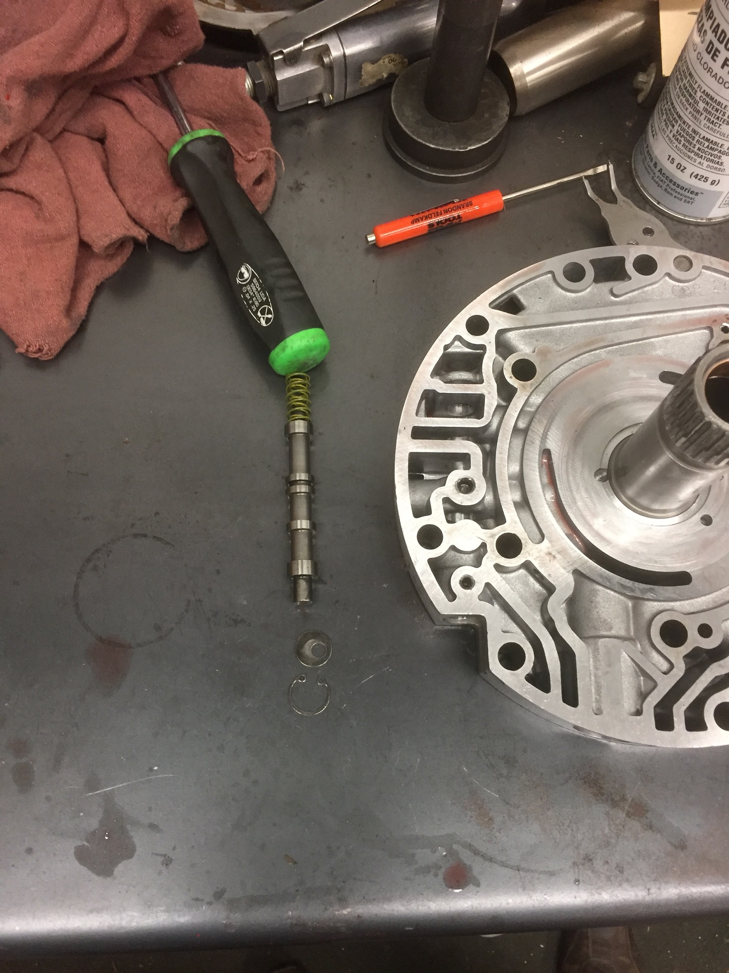
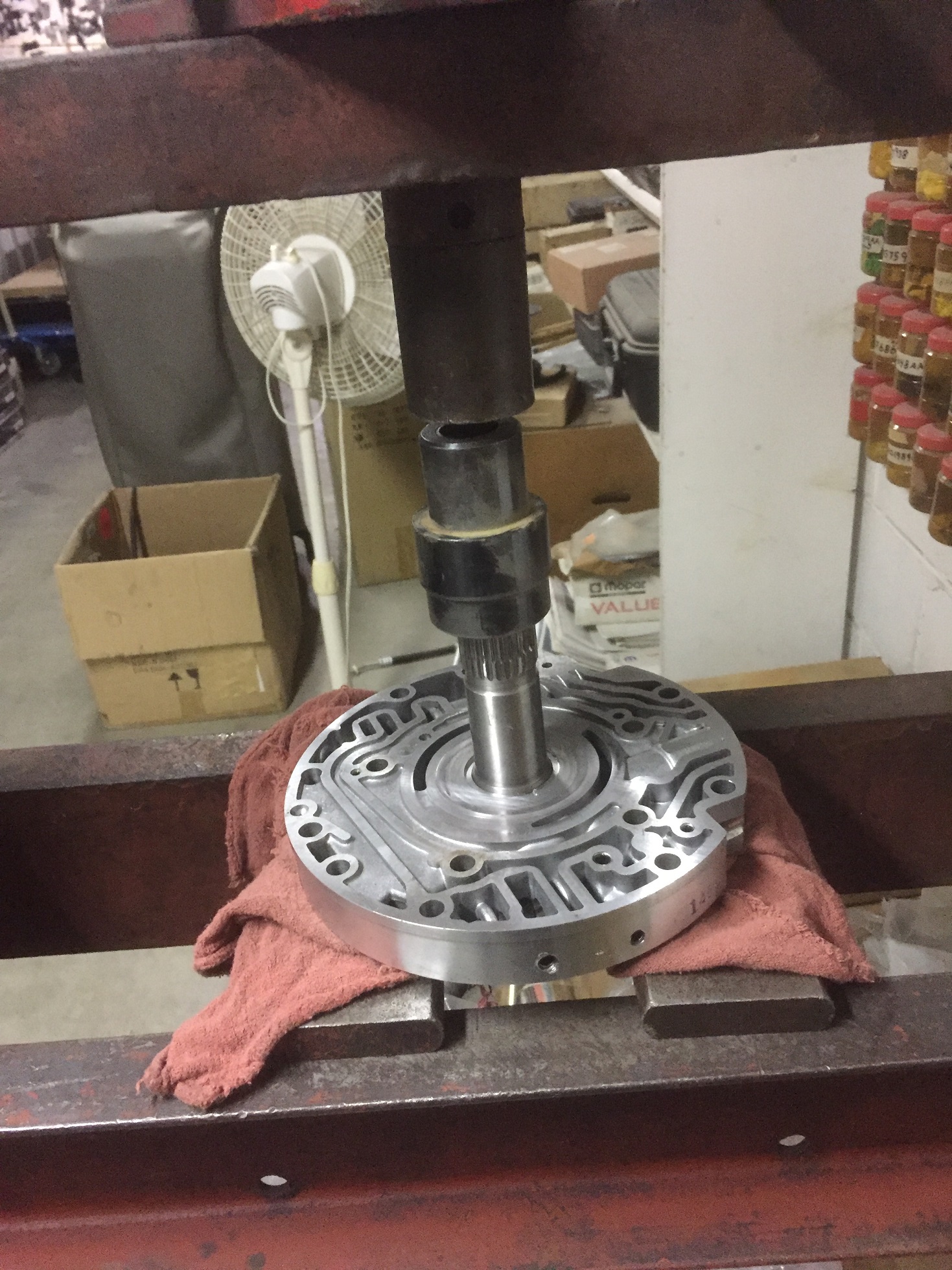
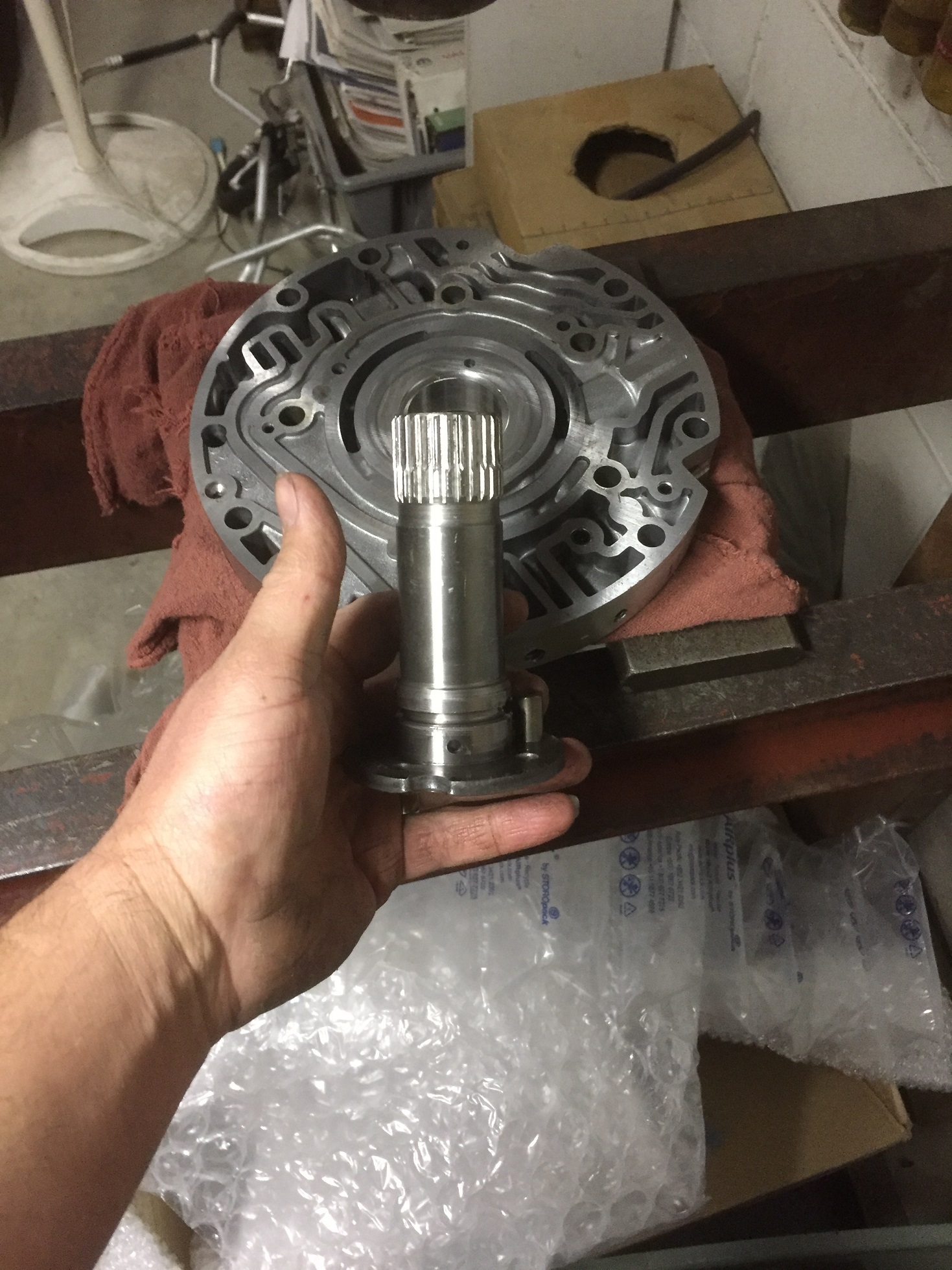
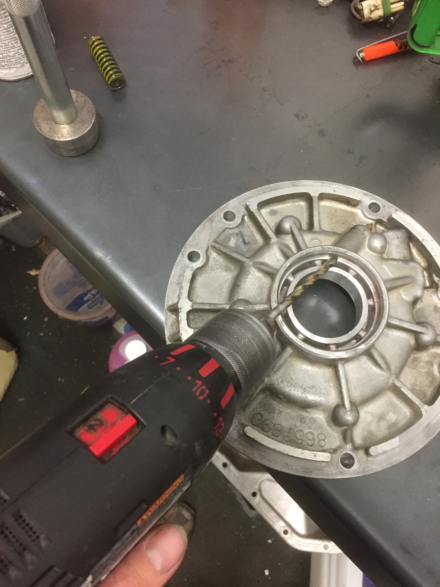
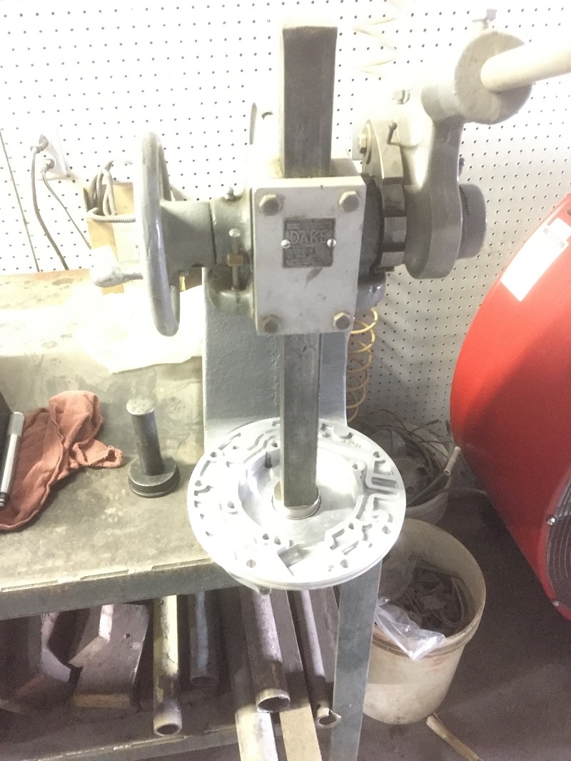
Remove the T27 screws holding the stator tube to the housing. If they become stripped you can grind a slot for a large flat tip screwdriver or grind it off completely and remove it after the tube is pressed out. PRESS the tube out using a hydraulic press (not a hammer), placing the supports as close to the center of the housing as possible while still allowing the tube to press out. Middle pic is a comparison of the original tube (note the wear on the splines) and a hardened tube. Hardened tube is cheap and should be done in every build, every time regardless of the condition of the original splines. If the pump has been apart before, it may have a hardened tube in it already. You can leave it in if the machined face of the aluminum housing doesn't need any work to it.
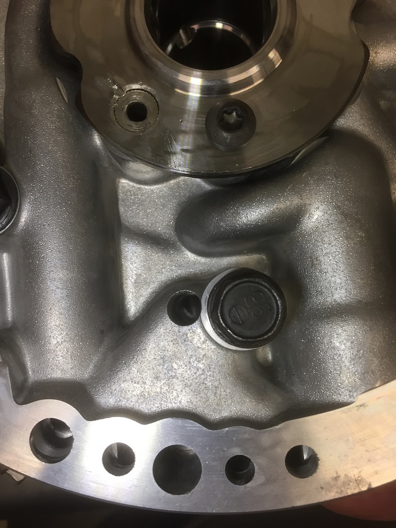
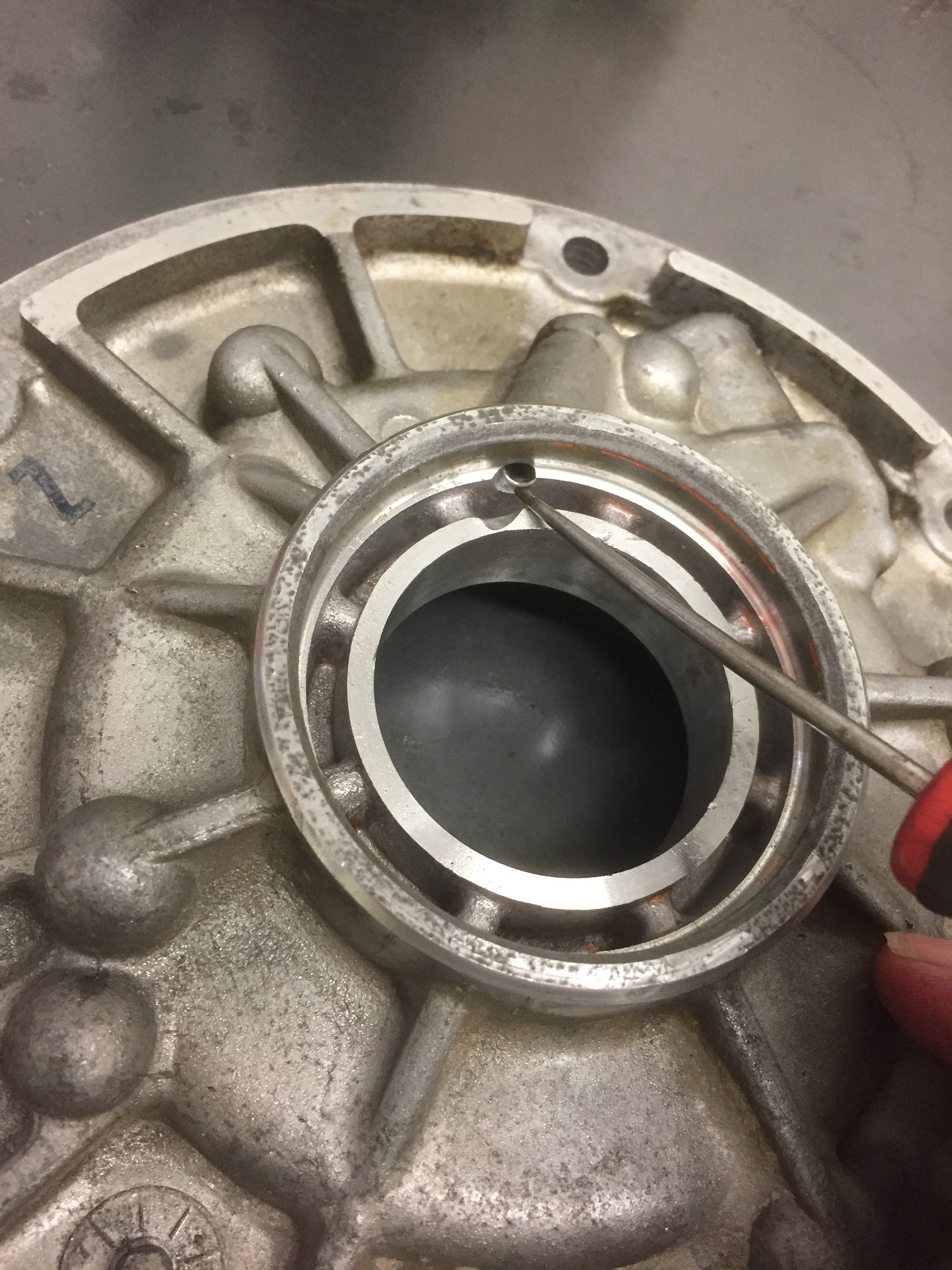
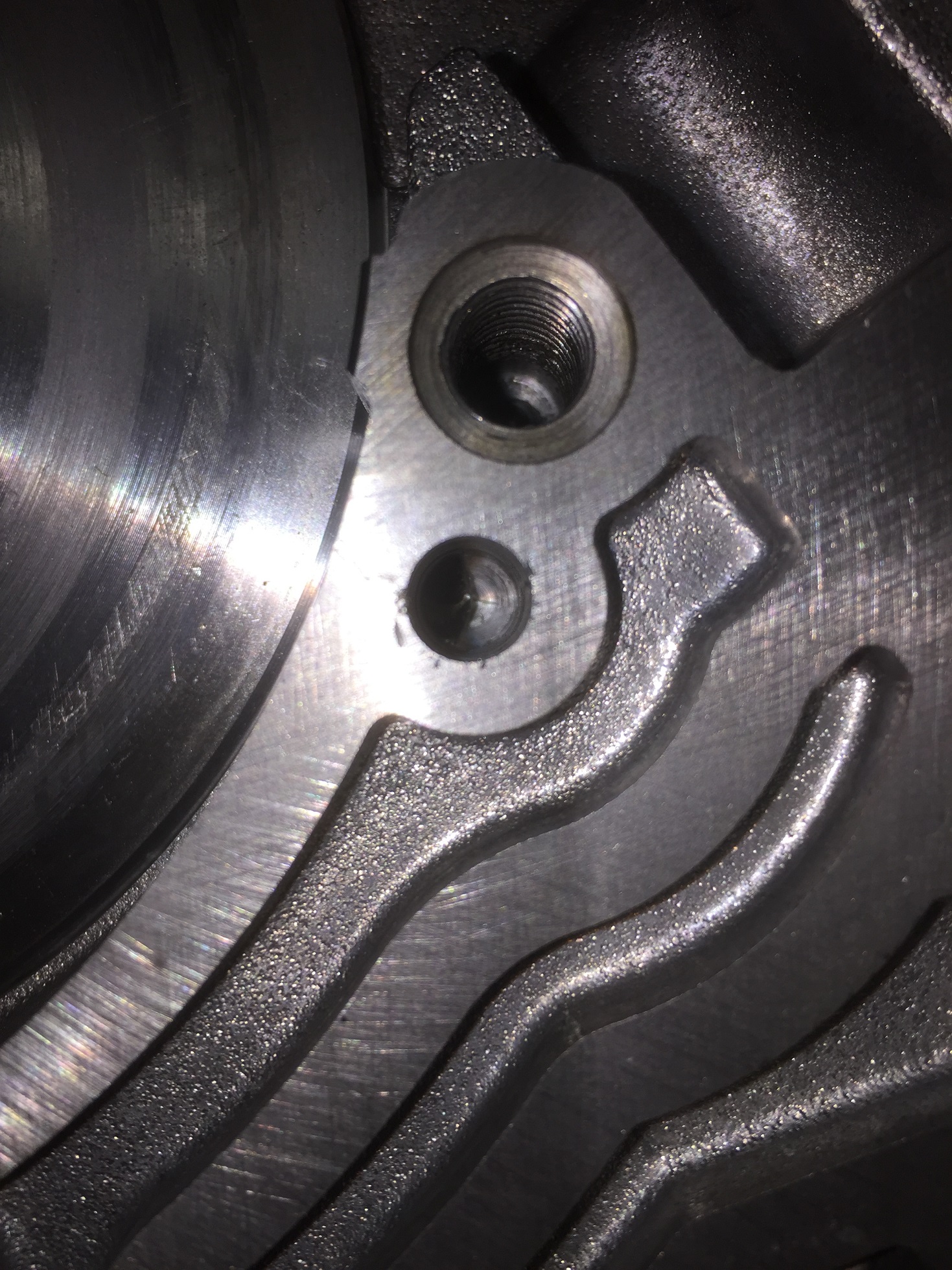
So at this
point, you should have two bare housings. Start by enlarging the 3 drainback
holes in the pictures below. This relieves pressure on the seal and prevents the
seal from leaking or blowing out of the pump body. There's a little bit of
debate here, some claim there's no benefit to it, I've seen plenty of evidence
that there's merit to doing it. I'll leave it at that. Besides, it's
FREE to do!
The two holes in the body
are obvious, but don't forget the mating hole in the cover.
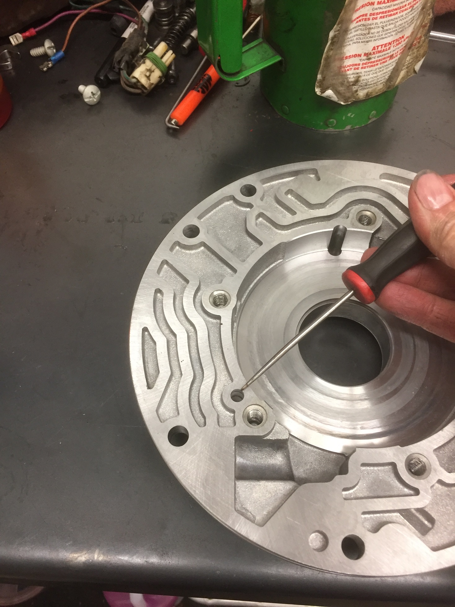
Don't be a hero, enlarge
them one or two drill sizes at a time and it'll go a lot smoother. Go to at
least 1/4". 9/32" or even 5/16" is better IF you trust yourself to do it and it
appears safe to do so, meaning if the passages are already drilled somewhat
crooked and you think you'll break through by going bigger, use your noggin and
stop while you're ahead! Chuck the drill bit out toward the edge of the
chuck to make it longer and easier. Use the intersecting hole as a visual guide
that you've drilled it far enough.
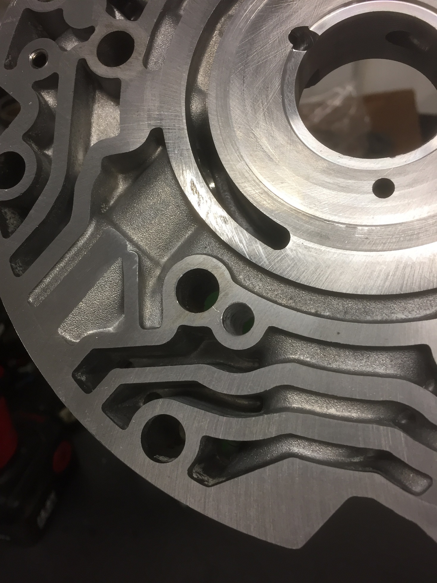
Using a
countersink or a deburring tool, make sure the holes are deburred well. This is
especially important on the two surfaces that mate together with no gasket. If
they aren't perfectly flat, you'll cause the whole pump to crossleak.
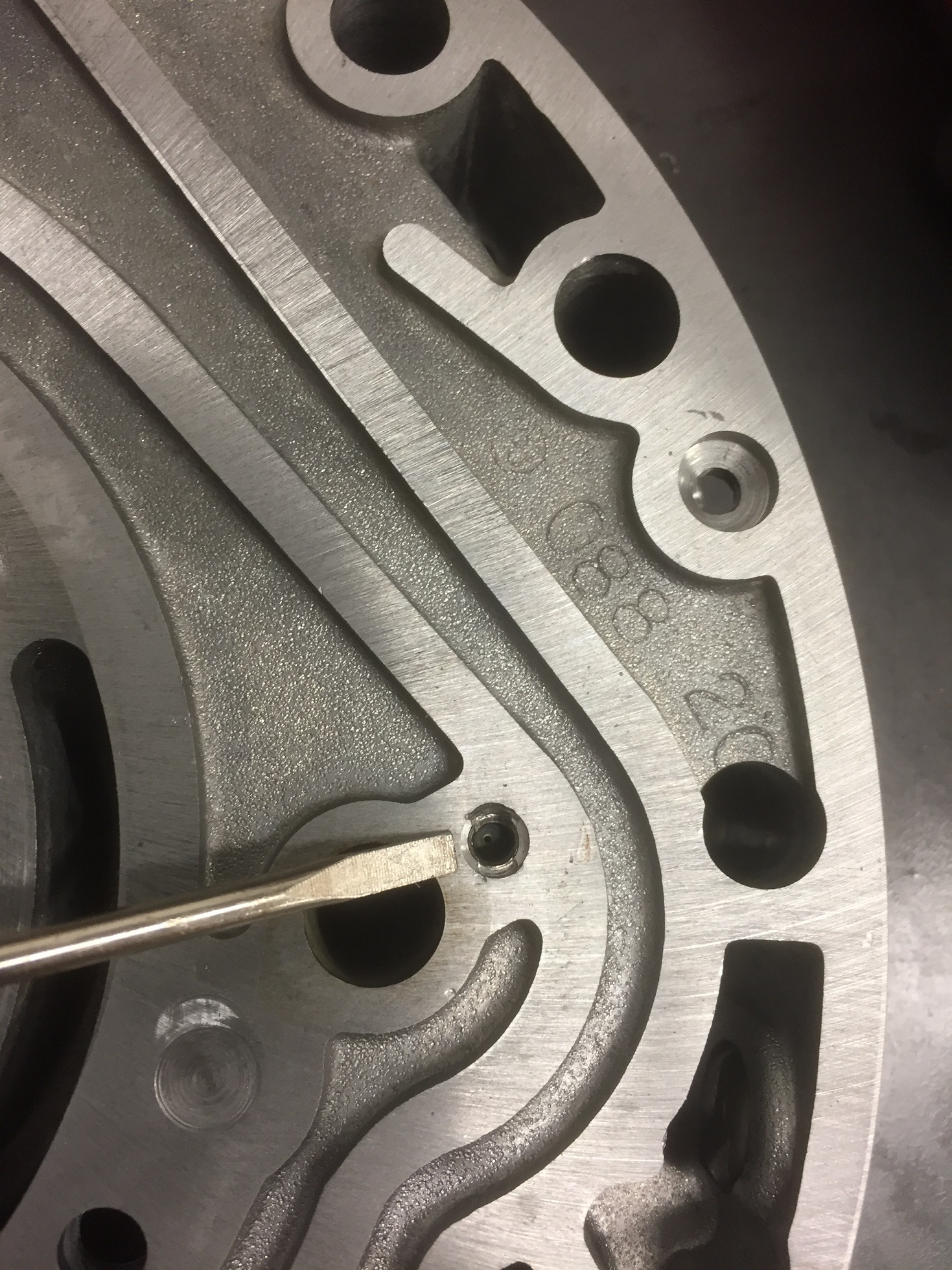
Now we deal with the
machined surfaces of the housings. There's no gasket here, so if these surfaces
aren't perfectly flat, you'll have cross leaks. From the factory there are areas
where the housings aren't flat due to GM staking the cup plugs in, If you check
these against the opposing housing you'll notice they fall into a cavity and not
the flat machined areas. They won't cause any problems if you have to leave them
alone. Second pic is of random damage caused by the housings being mishandled
after machining when they were new. If you can't flat sand the housings, you
need to at least inspect them closely for this kind of stuff (on all surfaces)
and use a whetstone to true it up if necessary.
Now, I happen
to have a pair of granite surface plates with sandpaper on them for flat
sanding. I realize most people who would actually use this tutorial don't have
access to this and must use a whetstone on a nice housing to get by with. You
should look into a cheap 9x12x2 granite surface plate though, they're pretty
cheap and even the cheapest ones out there are flatter than they need to be for
sandpaper. 9x12 accepts any old store bought sandpaper grit and comes in handy
for flat sanding everything engine/trans related. I have a fine grit and coarse
in 18x24. On the pump housing side, I just hit it quick and look for the sanding
marks to be even all the way across, indicating it's flat. Occasionally I'll see
raised areas around the bolt holes that need a little sanding to flatten out. I
don't know if this is caused by overtorquing or overheating or ![]() but
it's something to keep an eye out for. I hit this at the bare minimum because I
don't want to change the dimension of the pocket depth, I'm just verifying
flatness.
but
it's something to keep an eye out for. I hit this at the bare minimum because I
don't want to change the dimension of the pocket depth, I'm just verifying
flatness.
The next pic shows the
wear on the cover side housing that I'm going to sand out. As long as I turn the
housing often as I sand it, I can sand out a lot of wear here with no concern
for dimension change as it will stay parallel to the back side surface. First
pic is a straight edge with a flashlight behind it showing the groove from the
rotor. Second pic shows the wear from the slide as well as the rotor and vane
marks. This pump was out of a pretty damn decent trans, yours will likely look
the same or worse.
I ran it on
the fine paper just once or twice to highlight any high spots for pictures. This
shows the staked plugs and how much aluminum is raised by them. Third picture is
interesting. Remember the drainback holes I enlarged and deburred? Yeah, that
still wasn't flat. If you can't flat sand your housings, be DAMN SURE those two
mating areas are flat. Whetstone or equivalent method. The drill bit raises more
aluminum than you can see with the naked eye.
Sanding my arms off...and
a midway progress pic...
ALL DONE! If you look
closely you can see I didn't get the deepest groove completely out, but the
slide marks are gone and the groove won't catch a fingernail anymore.
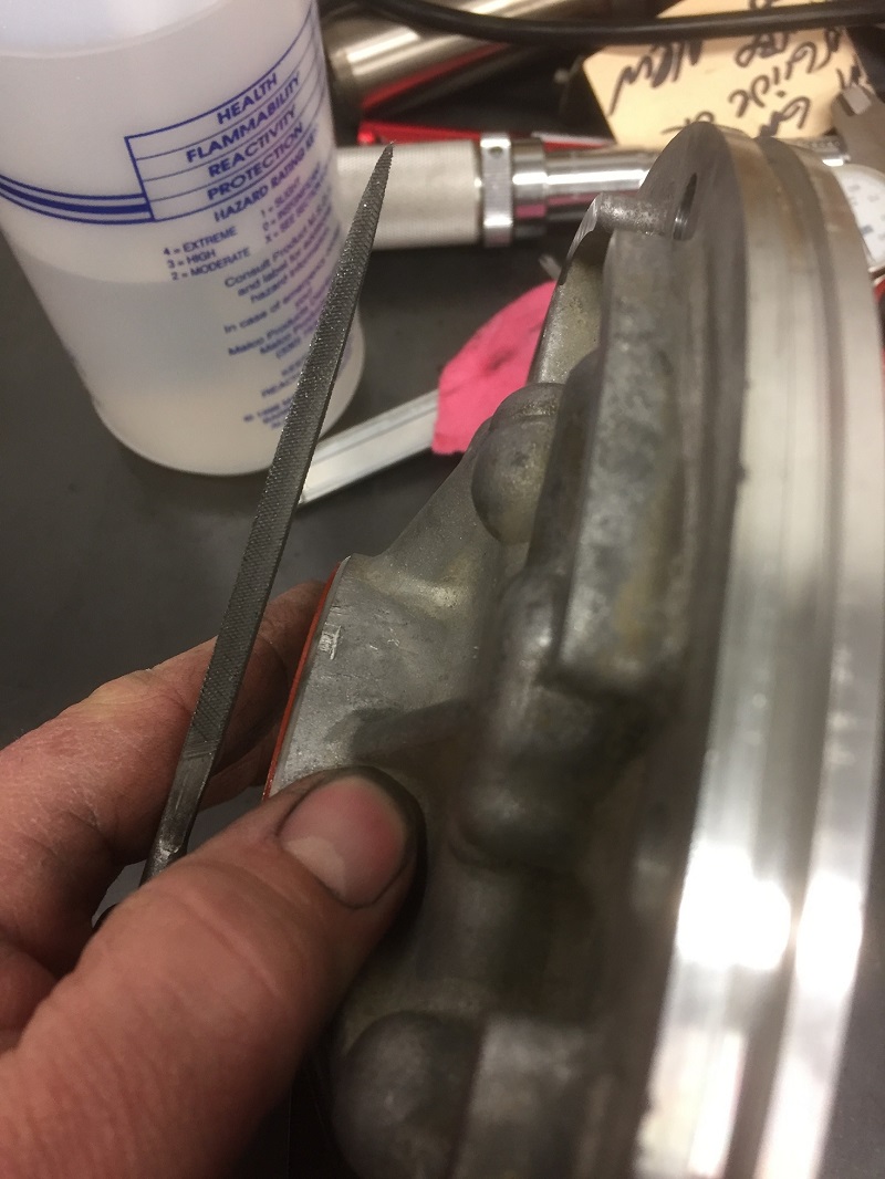
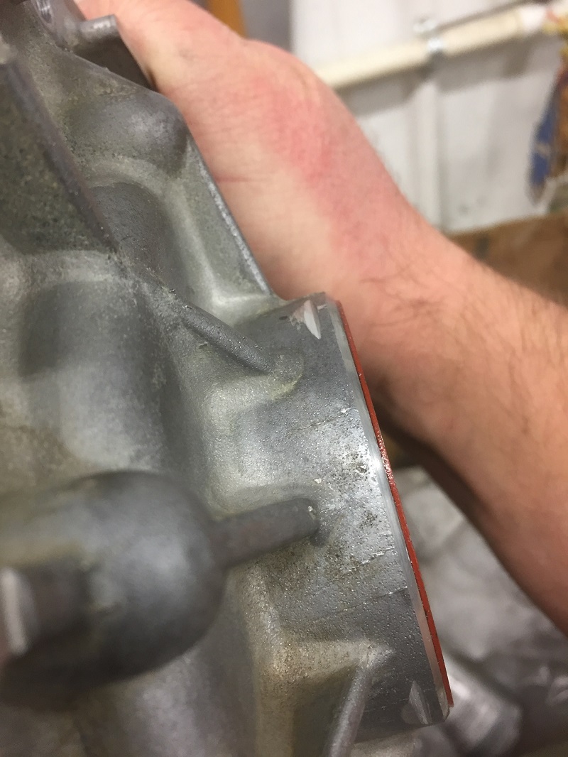
Now it's time
to notch the housing so I can stake the bushing in it. Using a round file, cut
two angled grooves opposing each other. You can do it without cutting into the
rotor guide area, I let this one dig in a little on purpose to illustrate that
it makes no difference if you do as long as its deburred. Note the notches don't
go all the way down the bore, we don't want to take away any more surface
contact area than we have to. *Some builders won't bother to notch/stake a 690
pump body due to the step in the front being able to hold the bushing.
Other's won't stake any of their pump bushings. I stake every bushing out
of habit, from the old 700 days. Here's a fine time to mention that I've seen a
couple of the 082 pump bodies that had the step in them just like the 690,
although it wasn't as pronounced. One of them is now in "usetaboost's" car.
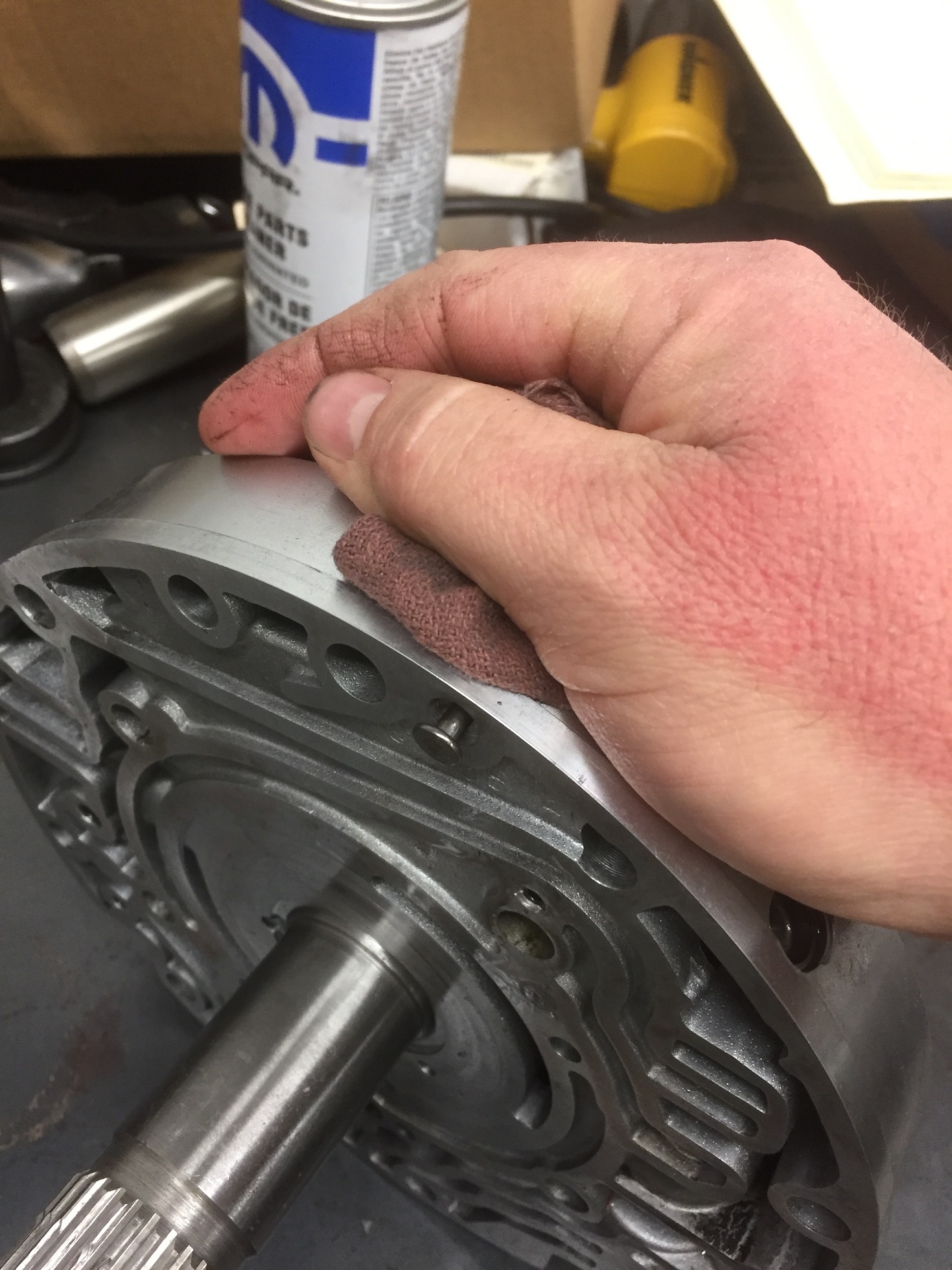
I'm not installing the
bushing yet, but I notched it now because I wanted it done before I "hand lap"
the pump cavity. *This is another area of builder preference. Some
builders won't touch the pump cavity. Some reading this won't trust
themselves to do it either. It'll work just fine if you don't. 400
grit sandpaper from a roll is perfect for this, it will break the glaze and
remove minor marks without changing the dimension easily. 600 would work and
might be better for a novice, I would think it to be damn near impossible to
screw it up with 600 grit. I use a few drops of trans fluid or penetrating oil
so the paper doesn't clog up, and then use my thumb in a repetitive circular
motion while turning the housing (yes, I'm left handed). First trip around the
housing, I scoot my thumb up the roll often, keeping fresh paper under it.
Second trip around, I leave the "dead" paper under my thumb for a smoother
finish. This was something I got good at in the 700 days and is second nature to
me now. Just try to get all the way to the outside of the cavity and sand it as
evenly as you can.
You can't see it well in
the above pic, but when rotating the housing in the light I can still see traces
of the original rotor marks. This tells me I didn't change the pocket depth.
This is done for the same reason you break any glaze in an engine or trans and
the reason you crosshatch a cylinder: Oil retention. Most used pumps will still
show a groove or two after sanding this pocket. As long as they aren't severe
they won't hurt anything or cost you any max pressure.
.JPG)
Now I surface the rotor
and slide. I start with the slide ring, leaving it in the slide with the old o
ring under it. On this pump I did a quick rub on the fine grit stone because my
280 is about dead. If it was a new sheet I might hit it on the 9x12 stone with
some dead 320 or finer after the 280. I really doubt it matters much, again,
this is just how "I" do things.
Now I remove the ring and
surface both sides of the slide and rotor....note the marks on the top side of
the slide aren't completely gone. They won't hurt anything. I might be able to
sand them out but it would likely alter the slide clearance in the cavity by the
time they were gone. Also should note: DO NOT try to sand the inner surface of
the slide where the pump vanes rotate. The slide is treated with a process
called Parkerizing, which is an anti-wear coating and even if it has some wear
showing, you'll do more harm than good by sanding on it. If most of this coating
is gone you should consider slide replacement.
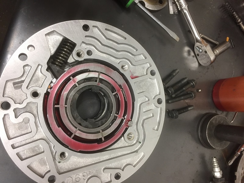
Now I'll give
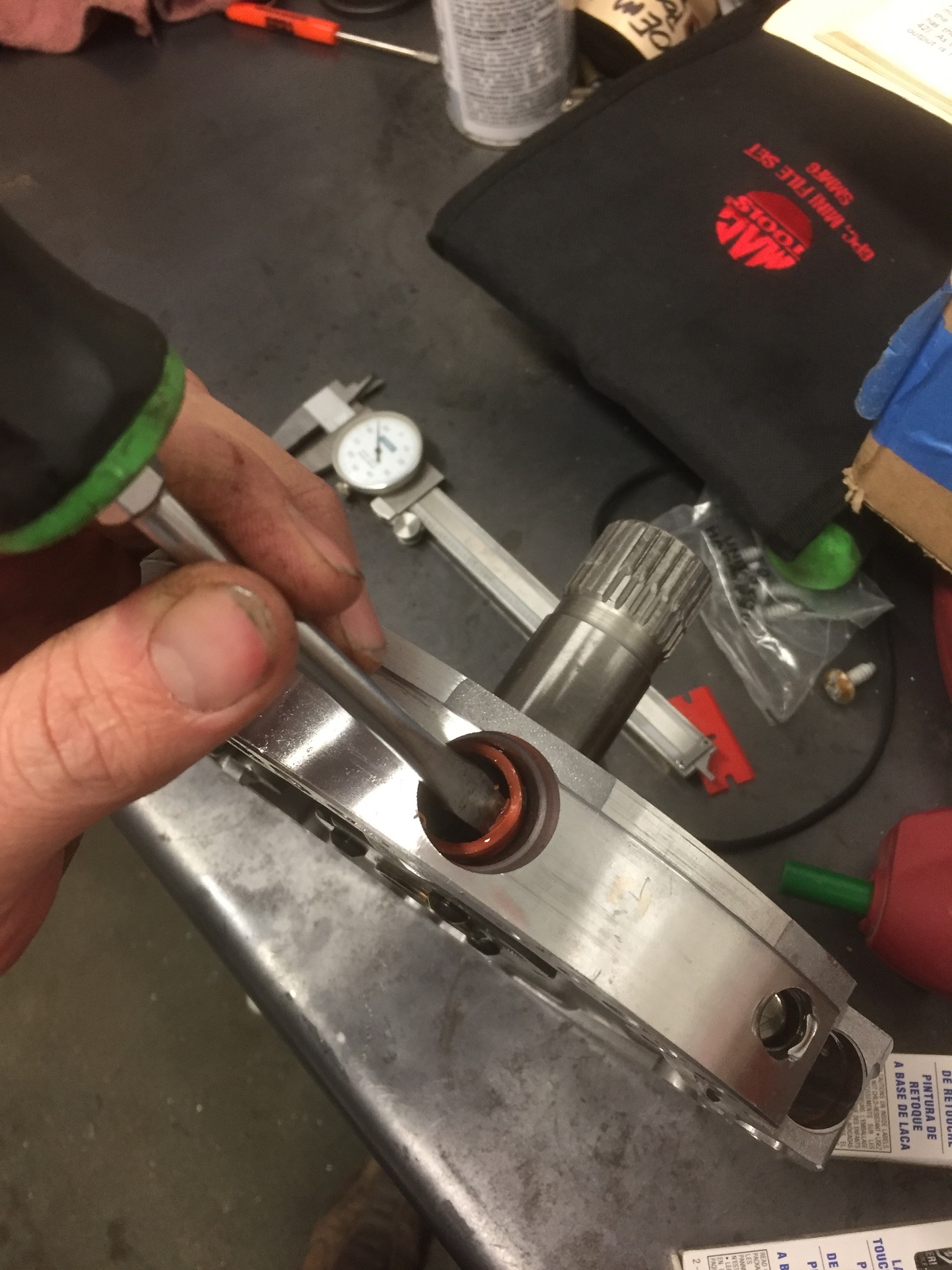
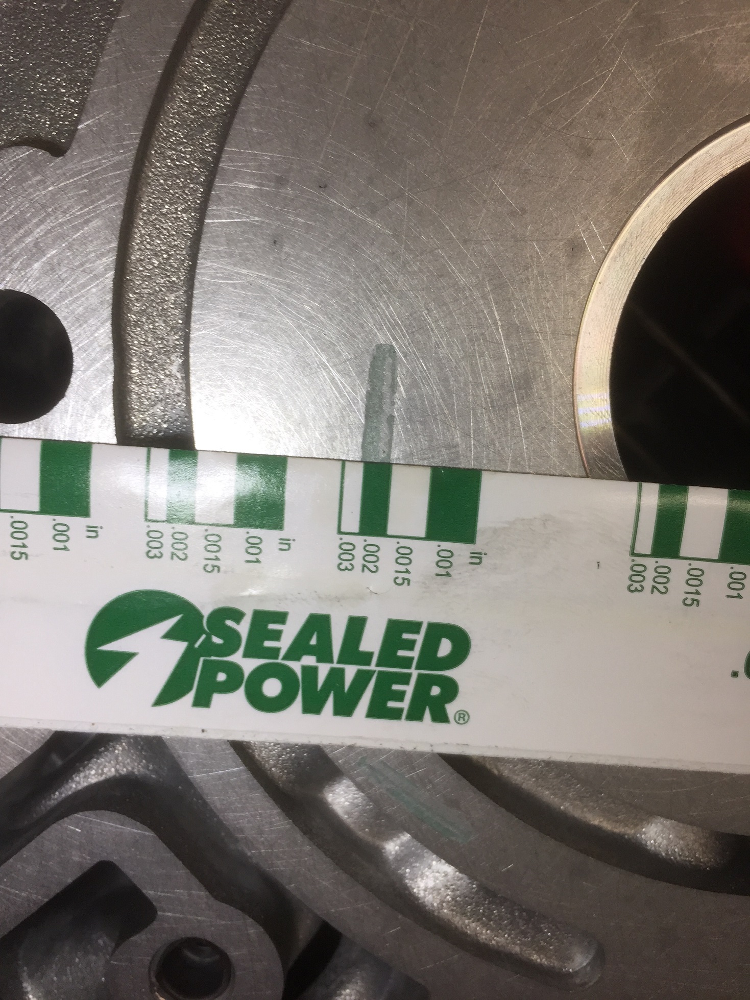
the parts a quick spray and check clearance with plastigauge. A strip of
plastigauge is literally $2 at the local parts store, go get a strip and use it.
I use three small strips of plastigauge on both the slide (without seal) and
rotor, then torque the cover on at 18 ft lbs. This one ended up right at .002.
Perfect. Steve V and Richard Clark have an alternate method of checking
clearance and Steve can chime in with it if he wants to share it.
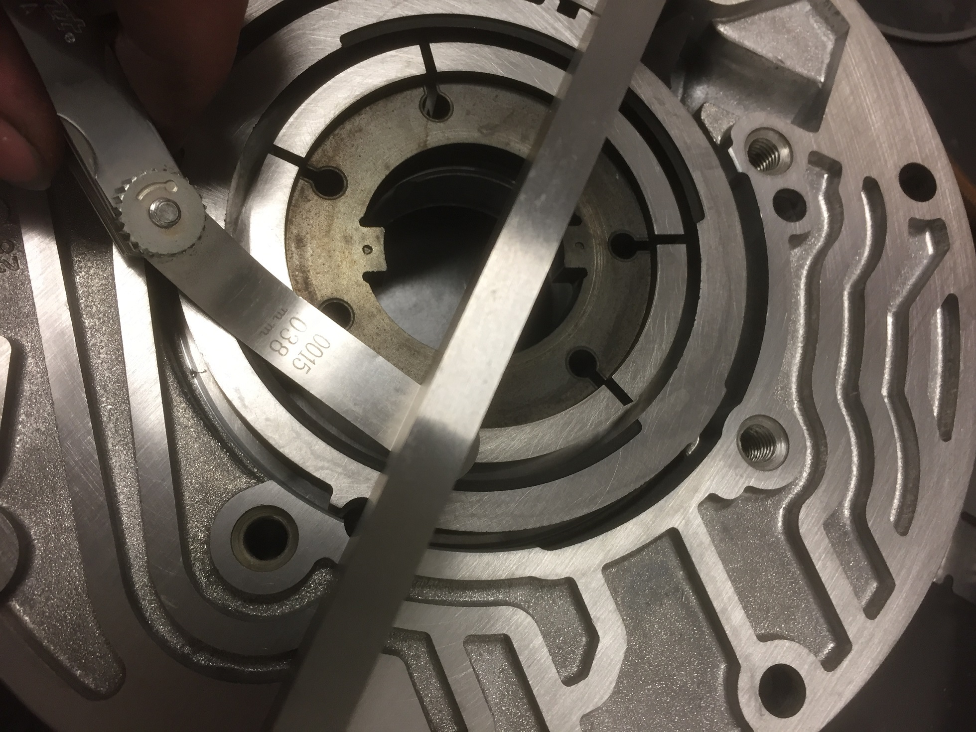
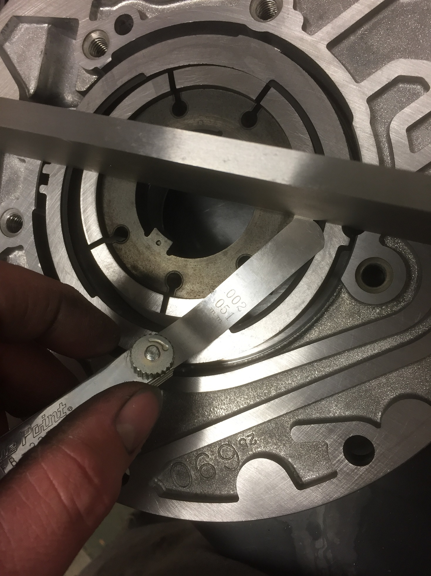
I checked it
with a straight edge and a feeler gauge which loosely verified the plastigauge.
1.5 thou barely fits under it in most spots and a .002 doesn't quite fit, but if
I lift the straight edge to place it under it, it doesn't have any wobble to it
when set on the .002. Ideal pump clearance is between .001 and .002. For
your average garage build, the slide can be quite a bit looser than that (.003
or more) because it has a positive seal under it. I've let the rotor be .0025 or
so before and never had any issues with pressure loss. I've always wanted to
assemble a "loosey-goosey" pump and see how it affected pressure but never have,
mostly since I have the ability to get it right. Maybe others will chime in with
more data on pump clearance vs. consequences. I do know if the slide is too
tight it will bind in the housing, the rotor would probably "self clearance" if
it doesn't break first.
Now that we have the
parts all surfaced and clearance checked, we can start the assembly. Spray both
housings thoroughly with brake clean and blow dry with compressed air. Let's
start with the pump cover/stator support.
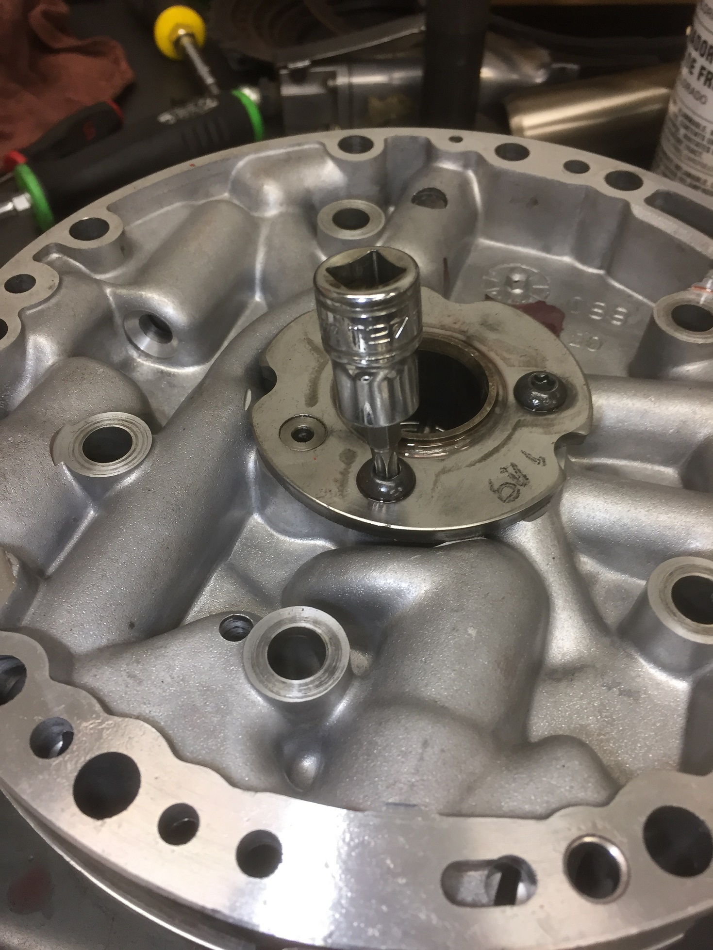
Grab the old stator
support and chuck it in a vise. Use an .045 drill to enlarge the orifice in this
cup plug inside the alignment pin. This increases lube oil to the "mickey mouse"
washer behind the pump. In the event you can't enlarge this, at least verify
that it's not obstructed and that it was punched cleanly from the factory. Note
about this cup plug: Not all of them are staked into the pin from the factory. I
have seen one fall out (was wedged sideways in the washer upon disassembly). The
pin is hardened and does not deform easily, so it is difficult to stake/peen the
opening to prevent this. If it's not staked, at least verify the cup plug
is seated well. Next pic is showing me removing the pin from the old
stator support with a punch.
Tap the pin
into the new stator tube, use something with a 90 degree angle to "eyeball" that
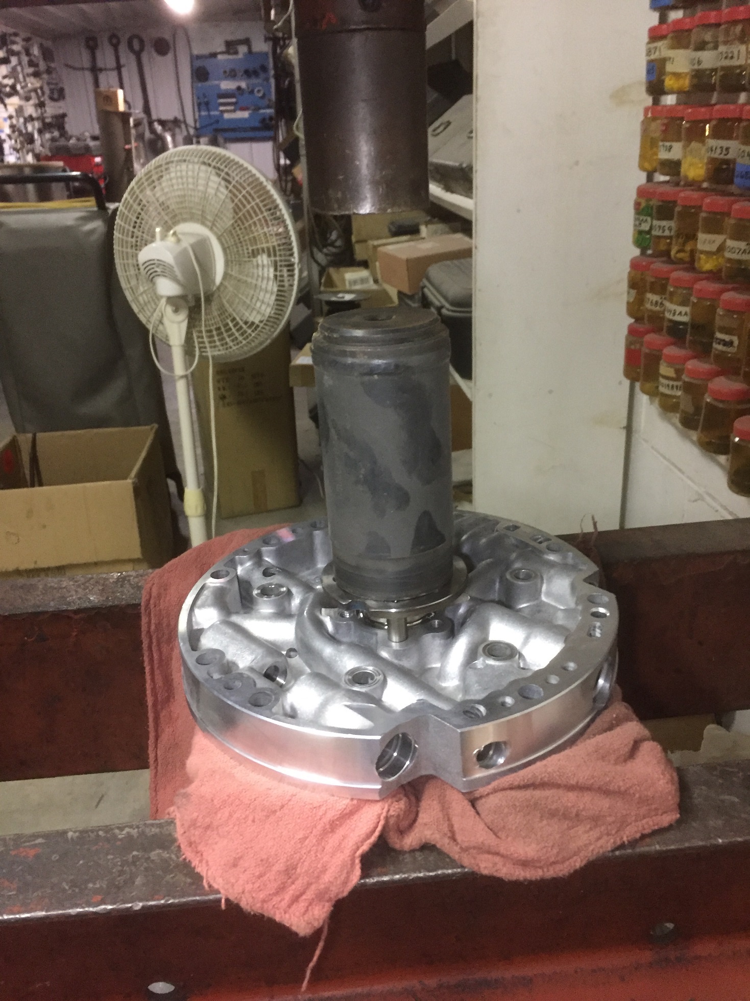
the pin is straight in the flange and parallel with the tube. PRESS the tube
into the housing (Again, no hammer) making sure the support plates under the
housing are positioned as close to the center as you can while still allowing
the tube to pass between them. A couple grease rags are a good idea to protect
your freshly sanded face from damage. If you're a novice and this task
gives you fits/makes you nervous, you can place the stator tube in the freezer
for a while and set the housing somewhere warm like on top of a heated parts
washer and it will slide in easier. Just keep an eye on the pin orientation on
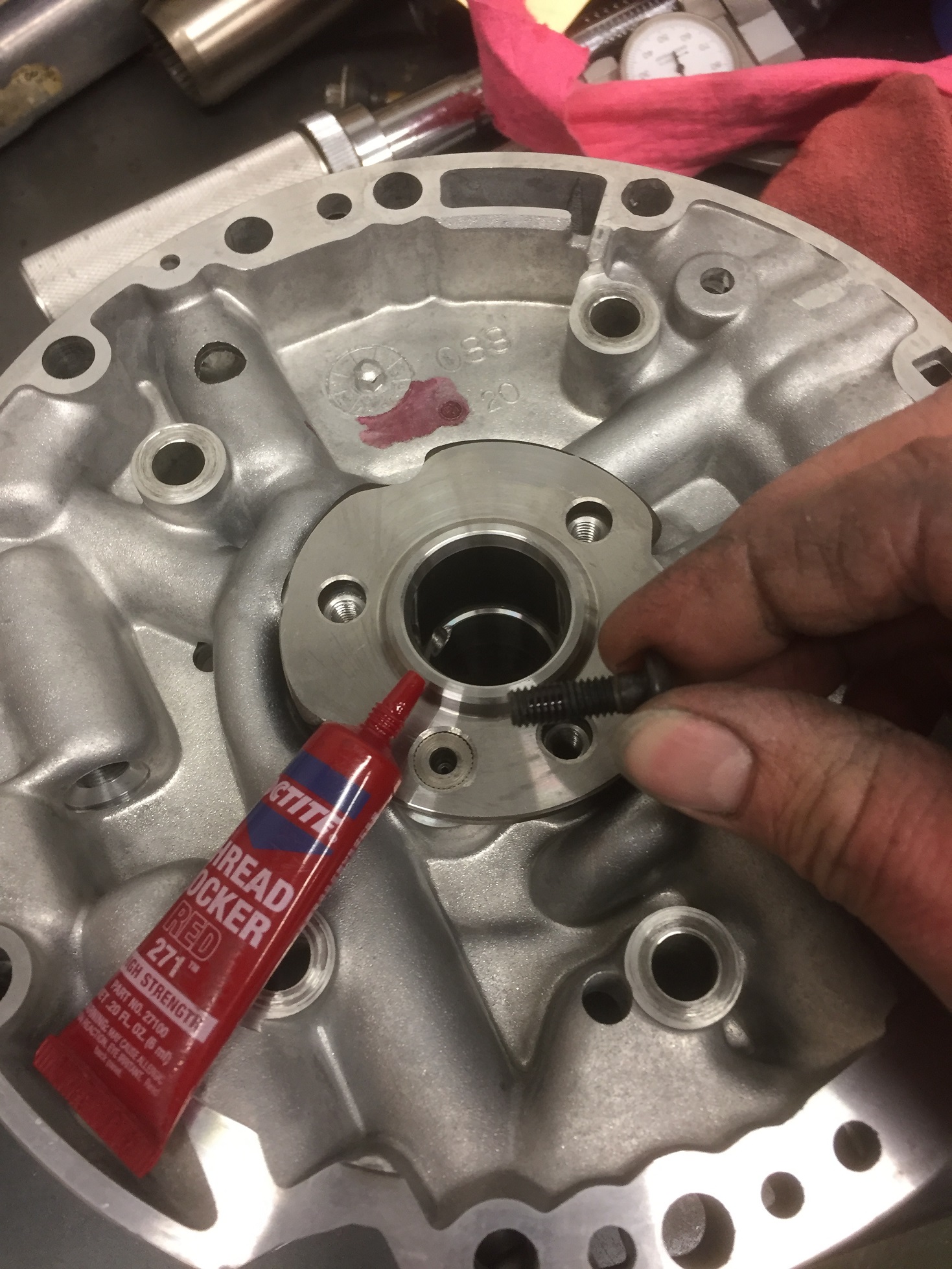
the way in. Clean the bolts and threads in the housing with brake clean and blow
dry. Apply a single drop of red locktite to the bolt threads, torque the bolts
to 10 ft. lbs. If the original bolts are damaged or if you have difficulty with
the torx head, you can replace them with an ordinary M6x1.0 thread hex head
bolt, just check the fit of the mickey mouse washer. I'll reiterate: CHECK
THE FIT OF THE MICKEY MOUSE WASHER if replacing the screws. Shortly after
writing this the first time, I helped a guy diagnose a front end play issue that
was tracked down to the bolts he was using here.
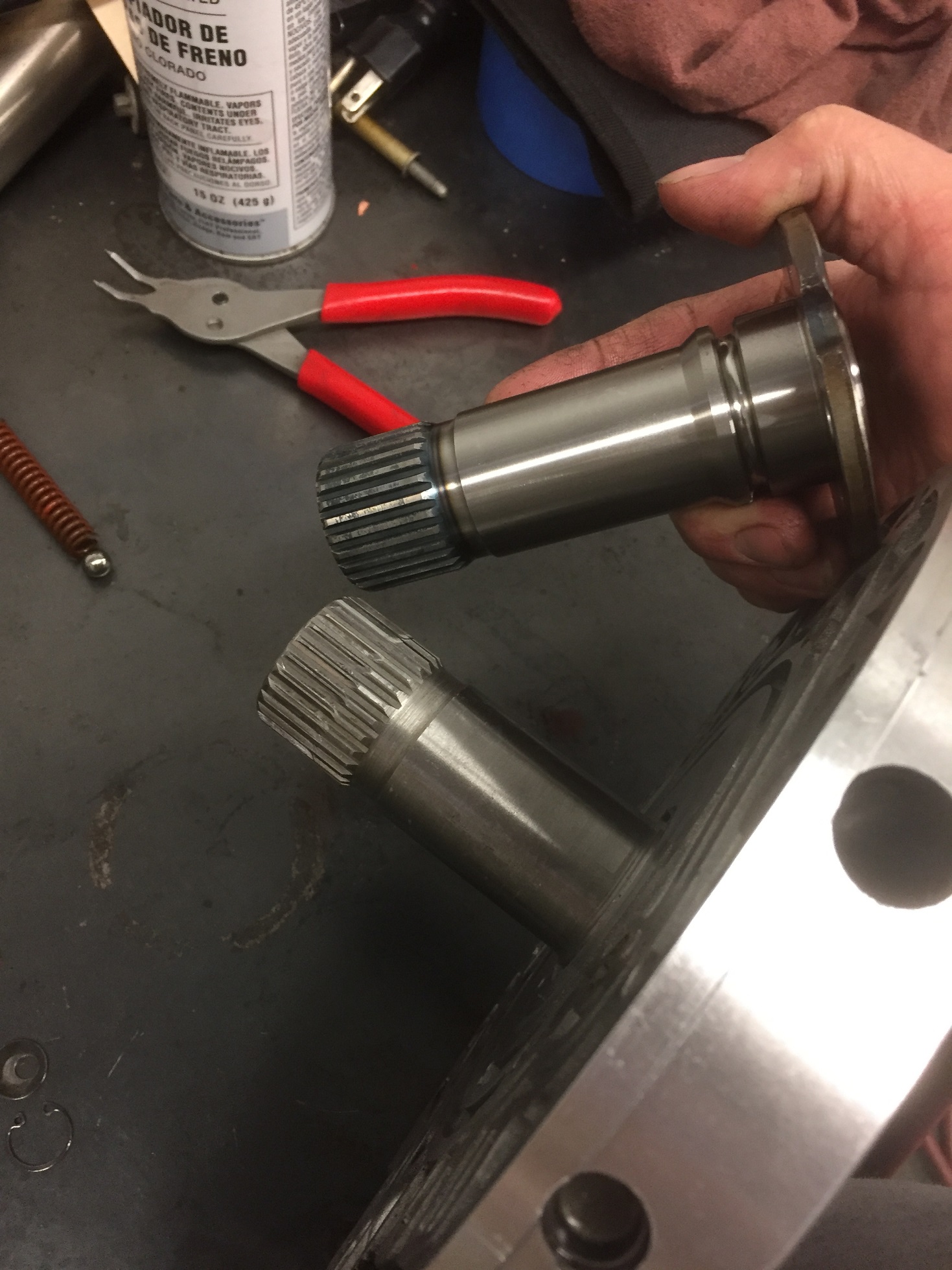
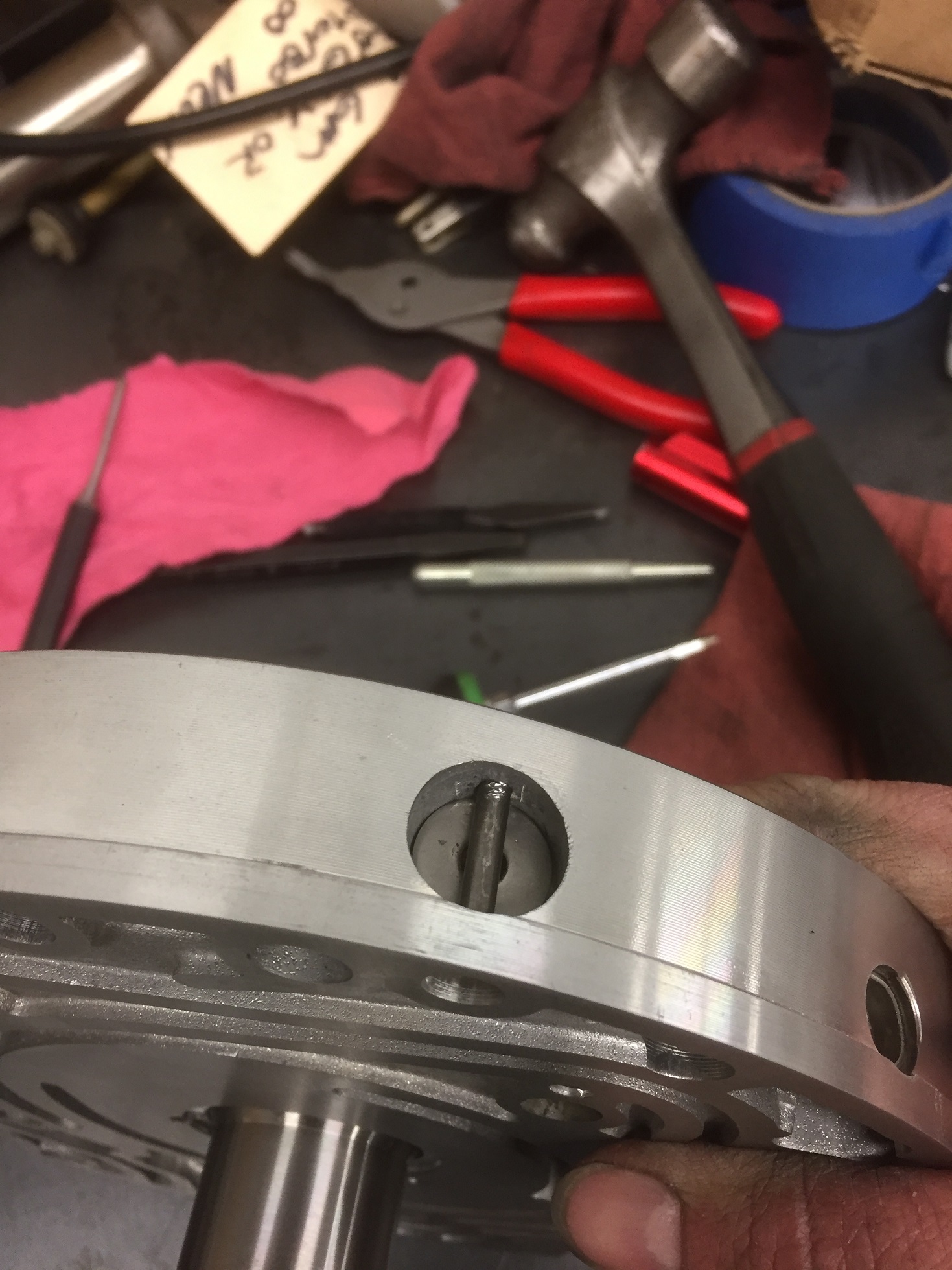
The stator tube pin is
hardened, but the tube flange itself is pretty soft metal and can easily be
staked with a punch to hold the pin from walking out against the washer. Pin
can't really go anywhere except against the mickey mouse washer once its
assembled, I stake it anyway. >BEATING THE HELL OUT OF THE PIN ONCE IT'S
ASSEMBLED COULD BREAK THE HOUSING BY FORCING IT THROUGH THE BOTTOM OF THE
ALUMINUM BORE. IF YOU DOUBT YOUR ABILITY, DON'T STAKE EITHER THE PIN OR THE CUP
PLUG INSIDE THE PIN. IN FACT, FORGET I EVEN MENTIONED IT (LOL)
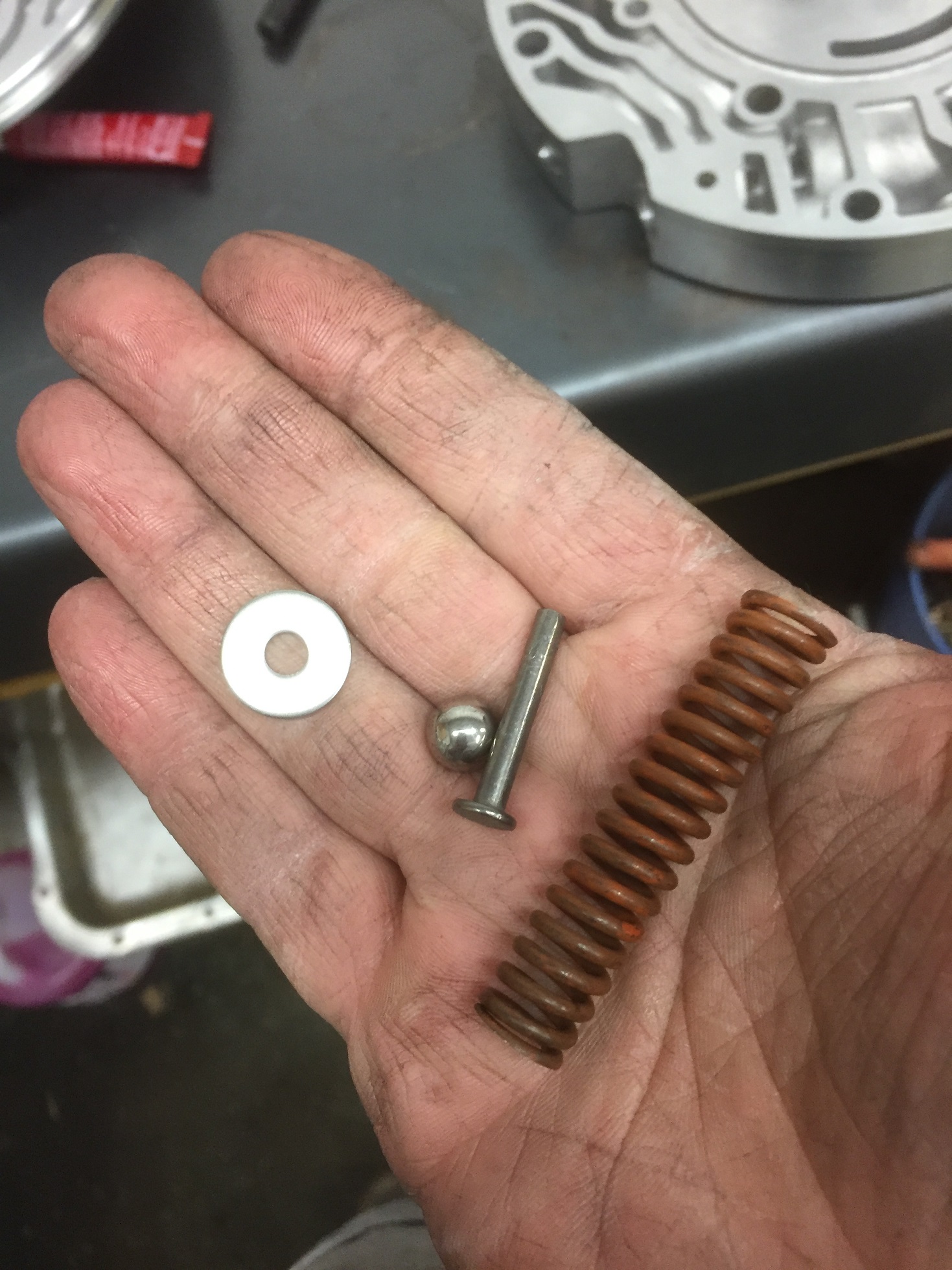
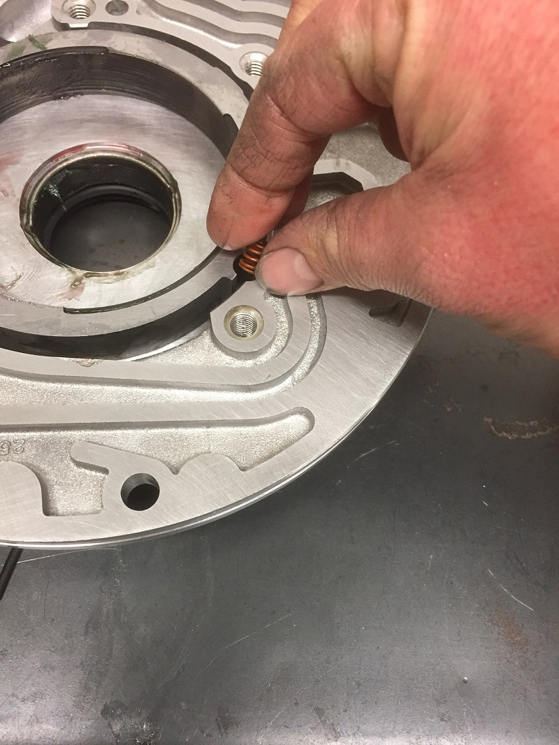
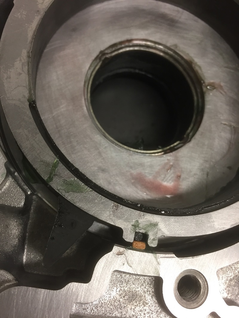
One problem
that happens with high pressure pumps, is that when we make enough pressure for
the pressure release valve (blowoff valve) to open, it can cause the spring to
start breaking 1/2 coils off where it rests against the narrow pin. This reduces
spring pressure and makes the ball open early, causing low max pressure and/or
pump buzzing. To solve this, insert a hardened washer between the pin and the
spring. An easy source for a washer is to get an extra lockup valvetrain washer
from another pump or your local trans shop (same as 700), it measures .040
thick. I use a stainless steel washer that measures .060, I only do this because
I have a whole stack of this washer here with no other use for them. I wouldn't
trust a mild steel washer here (use the lockup washer). I'd like to publicly
thank Dave Husek for this tip after I had this issue with the very first 200-4r
I ever built with performance in mind. Couple of the vendors carry a better
spring that also raises the blowoff pressure from ~260-270 to over 300 psi.
Clean, lube,
and insert the lockup valvetrain as it was removed, making sure the snap ring is
properly seated and that you can move the valve by pushing it with a small
screwdriver through the hole. If you are building a non-lockup trans, replace
this valve train with a non lock up kit and use their instructions. One area I
have no experience with is with the very early/diesel/export transmissions that
have a hydraulic lockup valve in the valve body. I don't have any of that here
so I don't know if any of this valvetrain is different. If someone else has this
info please post it here.
Here's the
part where I would normally install the Pressure regulator valvetrain and boost
valves, but apparently I forgot to order the damn things. For anything that
resembles a performance build, use an aftermarket PR spring, either the one that
comes with your shift kit, or order the purple TCI spring from summit or jegs,
OR if you're going super low budget and don't have the $11 plus shipping, walk
into any trans shop and ask for a transgo green PR spring. They probably have a
pile of them laying around (again, same as 700r4). ANY performance oriented
spring will be better than stock, I believe the purple TCI will give the highest
base pressure but I'll confess I haven't done any back to back testing.
On the
subject of shift kits, I highly recommend a kit from a known 200 guru. I
strongly DON'T recommend the green box transgo “noyoyo” kit intended for
ordinary passenger car use, especially the "bootstrap" tv plunger/valve setup.
It's the exact opposite of performance and even transgo knows that, because they
don't use that in their HD2 performance kits. Also along this topic,
you’ll hear me reference a max pressure of 260+. This write up will allow
the pump to be capable of making that pressure and survive while doing it.
The actual max pressure and pressure curve is dependent upon your shift kit
calibrations and carb/throttle geometry and that’s far beyond the scope of this
write up. Can’t stress enough that you should support the known gurus for
your complete shift kit, tailored to your specific needs. Sorry for the
derailment from pump tech.
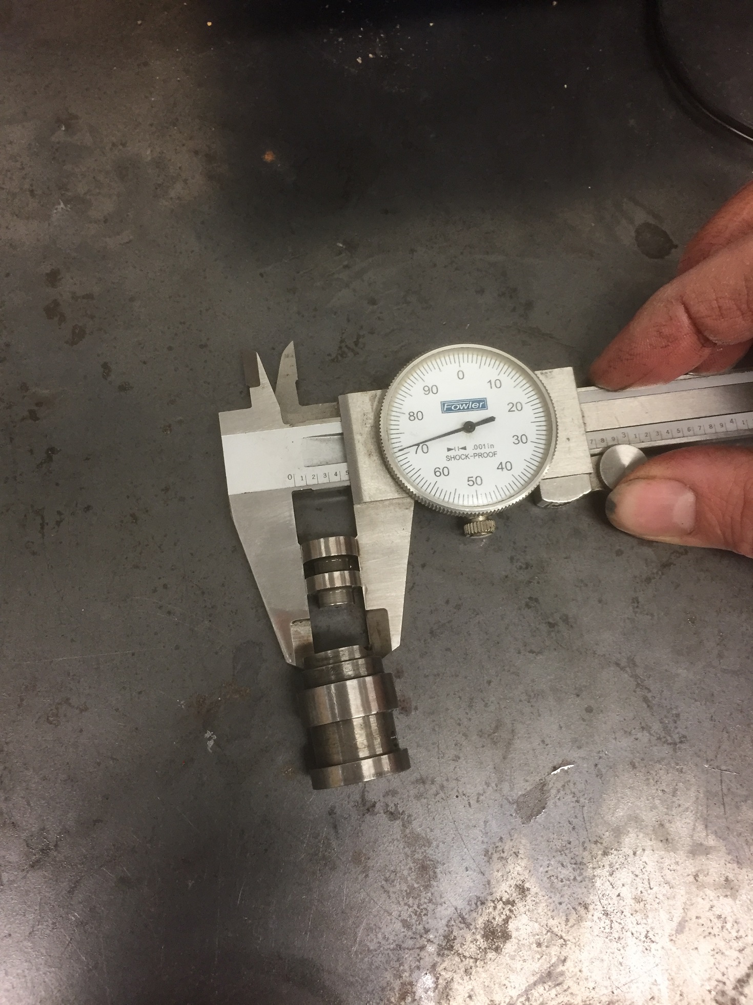
Boost valves:
.500 main boost valve is cheap, effective, and available everywhere. Larger ones
exist but the .500 will be ideal for anything built by anyone actually following
this thread (garage hobbyist). Reverse boost valve: if you've got the largest
factory one (one pictured above) it's fine for any garage build. Larger valve
here only gives you additional pressure boost in manual 1 and manual 2. Some
aftermarket boost valves have O-rings on the outside for better sealing in the
bore, it's builder preference though. The non o-ring factory style works fine.
Most of the valves are kind of hangy when new and I end up polishing the valve.
You can also polish the PR valve and lockup valve if they're scored up, just use
fine sandpaper (400-600ish).
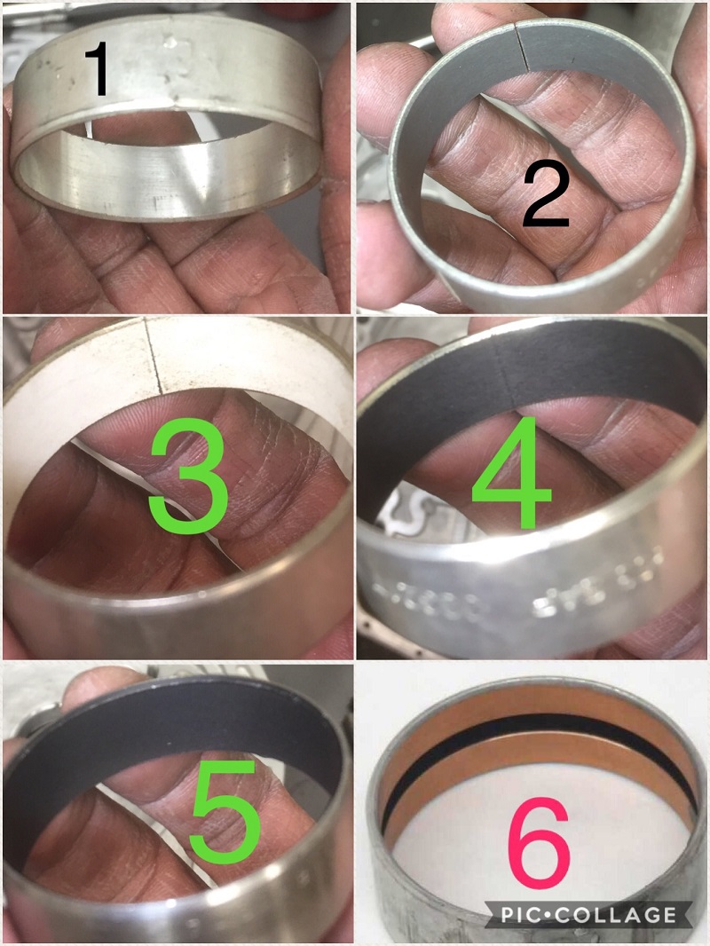
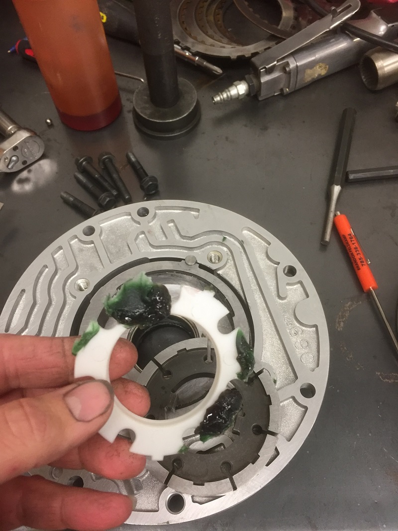
Pump bushing: Number 1 in the picture is the
OE style babbit bushing. Number 2 is the teflon bushing that trans shops used
for the better part of 15 years, and solved a lot of problems with, until one
day (circa 2012) they quit making them. I've heard a couple versions of the
story but my personal favorite was "they were shipping production of that
bushing overseas and the boat carrying all the tooling sank". Numbers 3,4, and 5
are the teflon bushings available today. Notice 2,3, and 4 are a split bushing
with a simple butted seam and number 5 is a solid bushing. Number 3 is a sonnax
bushing and I think number 4 was from transtar. The bushing saga unfolded after
I quit the trans shop and I can't honestly speak for which one of those two
would be "better" if any difference at all. I've used whichever one i'm holding
at the time AS LONG AS IT'S A SPLIT BUSHING. I've tried pressing the solid
bushing (number 5) in on a couple different occasions, and both times they were
tight on the converter hub and I didn't use them. I've heard others report
the same findings. Number 6 is a "sure seal" bushing by teckpak/fitzall,
note it has a rubber o ring in the middle. This is an attempt to keep oil from
pushing the front seal out. I've never ran one, as my former boss/mentor told me
to run far, far away from them. I'd rather do the proper drainback/seal mods. I
wouldn't be surprised if there's a bushing or two I've missed or if there's a
cheap knockoff of the split teflons out there somewhere. Anything that's the
same as a 700/4l60e and needs replaced in every build is bound to have a wide
variety of options.
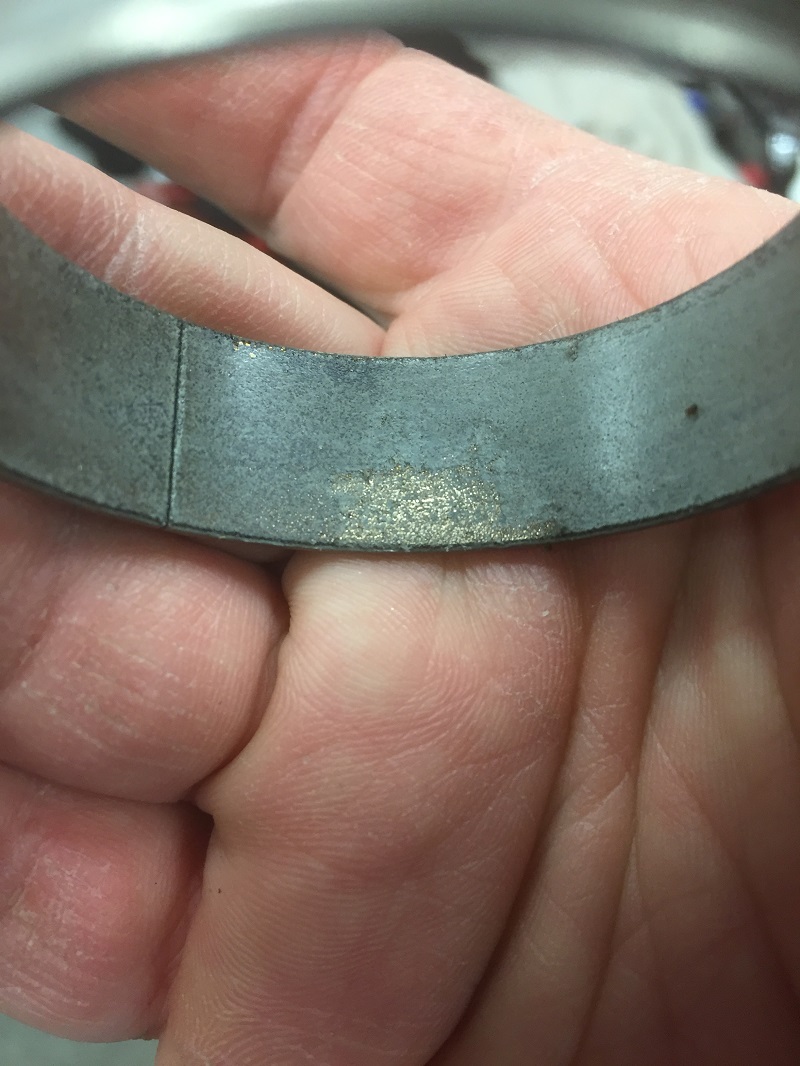
Numbers 2 through 4 are actually a porous
bronze bushing with a teflon layer on top/in the pores of the bronze middle
layer. I'm including pics of a used one (one of the good gray ones) that
actually outlasted the pump it was found in. I scraped the top layer off
to show the porous bronze layer underneath. These gray ones really are
gold if you can find them. Maybe they'll retool them someday. I did
the same thing to a solid (number 5 in pic) bushing and it's just as suspected,
a cheap soft bushing with a quick teflon top layer. JUNK! in my opinion.
Again, any veteran builder with feedback on
current bushing selection can feel free to correct or elaborate on anything I've
posted. When I was doing 700 pumps, it was bushing number 2, ordered by the
dozens and they just worked. I'm now out of the loop I guess.
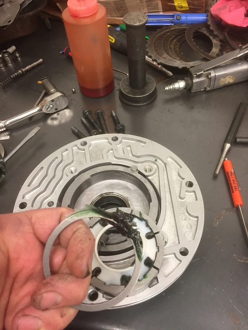
So before pressing in the bushing, make sure
the housing is final cleaned for assembly. Take some scotchbrite and clean the
residue out of the seal bore, and check it and bushing bore both for any stray
screwdriver/chisel gouges and correct as necessary before brake cleaning the
hell out of the housing and compressed air drying it. I'm anal about surfaces
being truly clean for things such as loctite so I take a paper towel and some
denatured alcohol and wipe the bushing/seal bores clean as well as the outer
surface of the bushing itself.
Now, to be "correct" here, you are supposed to
use green sleeve retaining loctite for something like holding a bushing in the
bore. However, red high strength is what everyone has laying around and I've
honestly never heard of anyone using anything else, even if it's not "correct"
and it works just fine in conjunction with staking the bushing inside literally
thousands of daily drivers every day. A light, even coat spread around with your
finger is best here, putting too much on only makes more to wipe off after it's
pressed in/staked. An arbor press is your ideal tool, but it can be done by
hammer and driver and I assume that's what you're going to have to do in your
garage. You can use a wide flat driver to get it started and then use the
correct driver or equivalent to get it seated the rest of the way. Oh, and make
sure the split of the bushing is indexed approx. halfway between your notches
you filed.
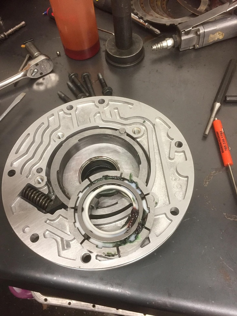
690 pump body, press it up to the factory lip
but don't hammer on it once it touches, as it can absolutely be forced past it.
check fit on the torque converter, or if for some crazy reason you don't have a
converter neck, use the small end of the center support (same dimension as
converter neck which is why you can use the teflon pump bushing in the direct
drum). On the earlier pump bodies you want to center the bushing in the bushing
bore.
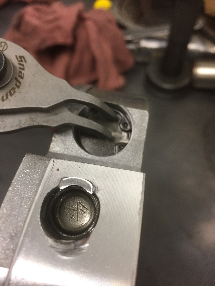
We now stake the bushing. Use a small roll pin
punch, holding it exactly like i've pictured will make your life easier. Use
your leg and/or beer gut to hold the body against the bench. I'm (still) left
handed so you may need to mirror this image. My index finger is keeping the
punch from contacting/nicking the freshly sanded housing, my ring finger is
right against the tip of the punch, preventing it from slipping down the
bushing. My thumb is keeping it from slipping into the pump cavity. Try it that
way and thank me later. Note that on this pump, the bushing is slightly recessed
in its bore and there's a distinct lip there. The 690 pump body has a deeper
bushing bore than the early cast. Earlier castings, your bushing should be
perfectly centered in the bore (as I've already stated once).
Take a razor knife or pocket knife and clean
up any burrs or teflon dingleberries, and then wipe up your excess loctite
before it dries. (I've already installed the front seal in these pics because my
bench isn't close to the arbor press and I wanted to save steps.)
For the front seal, back in the day we used to
go through an arduous process of taking the seal to the wire wheel and cleaning
off all the original "boretite" coating, then taking scotchbrite/brake clean to
clean off the remaining residue, then wiping it clean and applying a healthy
coat of red loctite to the bare steel and then using the seal retainer after the
seal is in. I don't do that anymore and i'll show you why here in a minute. I DO
still put a thin coat of loctite on it out of habit but it's probably not
necessary either.
SO, press/drive the seal in using the proper
wide, flat driver....
..or if that's not available, the original
stator tube fits it like a glove...
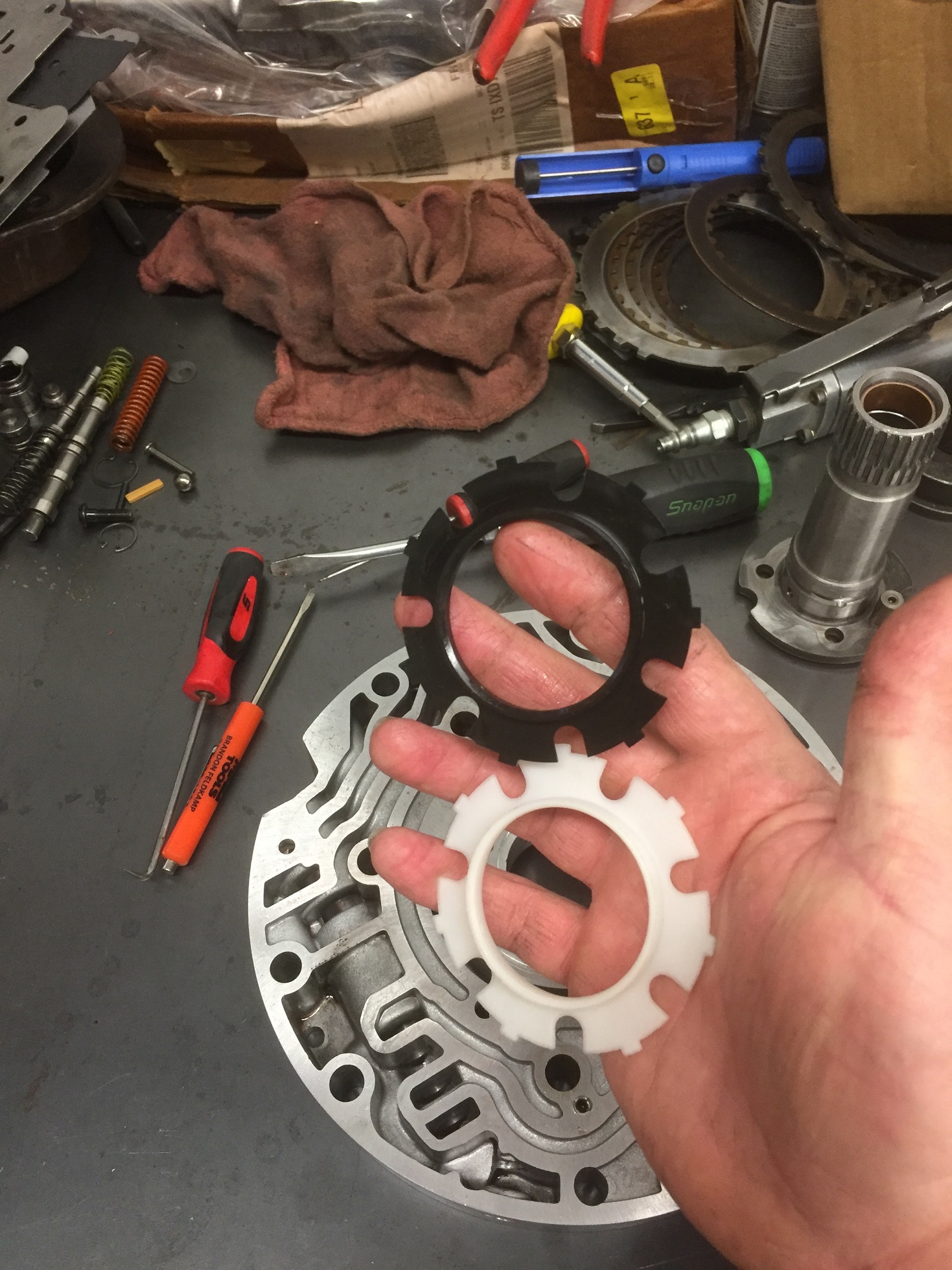
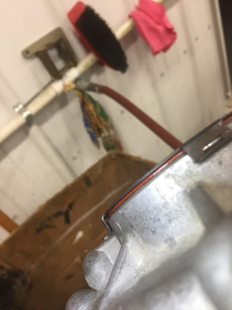
Now, index a 700 seal retainer until you find
a spot where all 4 tabs go on and miss all the ribs. Then tap it on with a
hammer. NOW, take your bare fingers and pry that damn thing right back off,
crack a beer and stare at that design for awhile, realize that it can barely
hold itself on, let alone hold the seal from blowing out. When your beer is
gone, get out your mini file set and fix the design.
Using the 4 witness marks as your guide, file
4 notches in the housing to give the retainer something to grab on to. This will
take some finesse, your choice of file and the angle you hold it at makes or
breaks this project. You want to back cut it in a way that leaves the metal
finger a 90 degree edge to grab/lock on to. Test fit the retainer and file the
notches higher up the casting, until all 4 fingers lock on good.
Not going anywhere now!
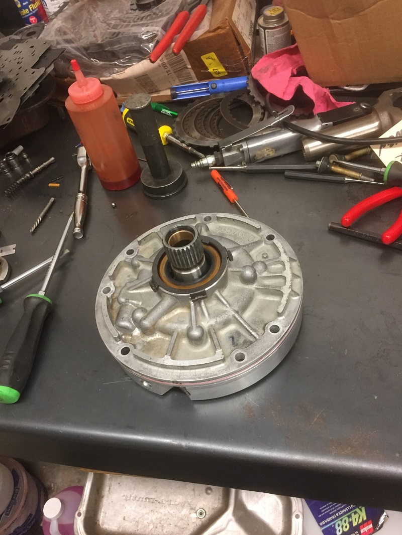
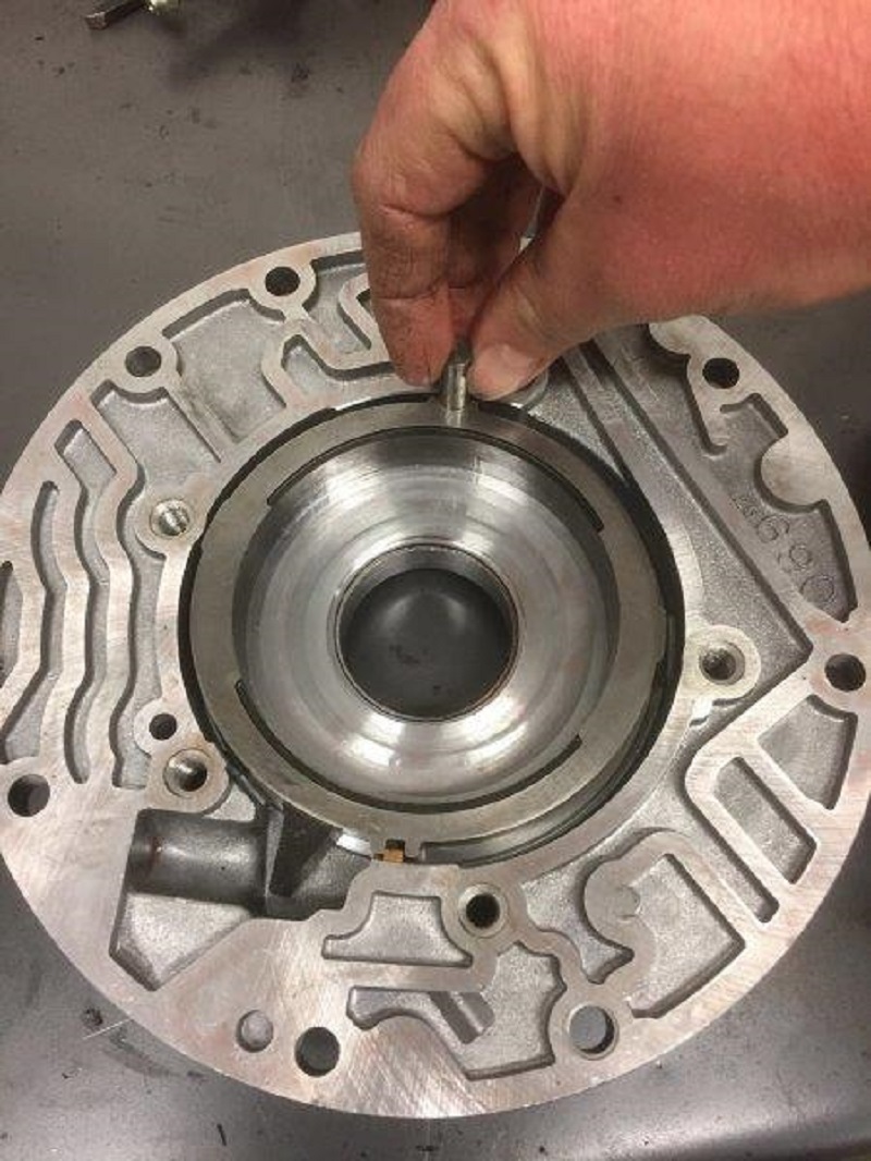
Pump assembly:
Obviously, clean all parts thoroughly before
assembly. Insert the rubber o ring into the slide with some assembly gel (or
petroleum jelly), then use the gel to "glue" the slide ring in the cavity with
it, keeping track to put the surfaced side out towards the housing.
Now's a fine time to lube the bushing and
spread some lube around the cavity a bit, then set the slide in the cavity
(steel ring side goes down).
Don't forget to install the small spring into
the cavity under the pivot pin
Install the slide seals as shown. The square
seal is the actual seal, the round part holds it tight against the pump cavity
wall. Depending on the brand of your kit, your new seals may protrude out of the
cavity and if so, will need to be trimmed off with a razor blade.
Insert the slide pivot pin, making sure the
seals on the opposite side stay in their proper place.
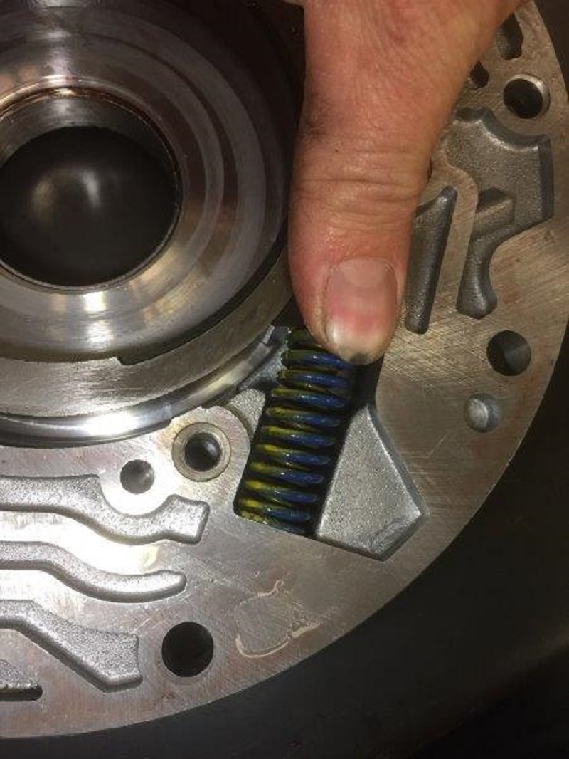
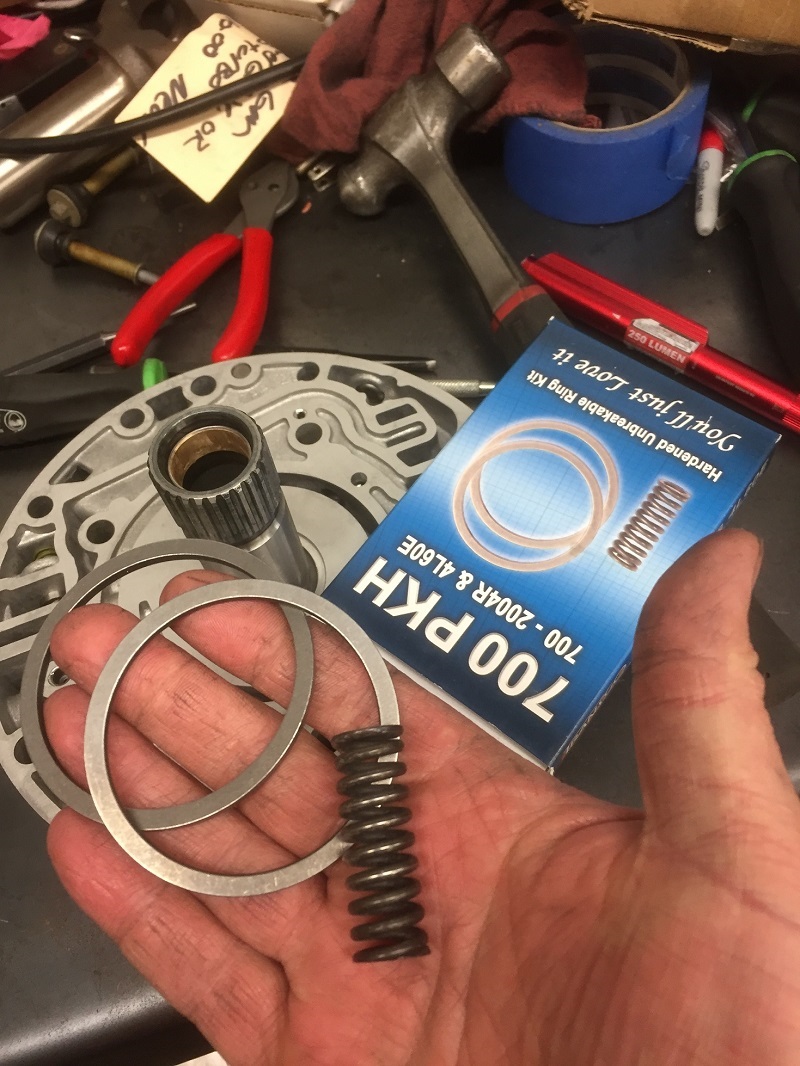
You will need to purchase a transgo 700-pkh
hardened ring/spring kit. They're cheap. You need the slide spring out of this
kit at this time.
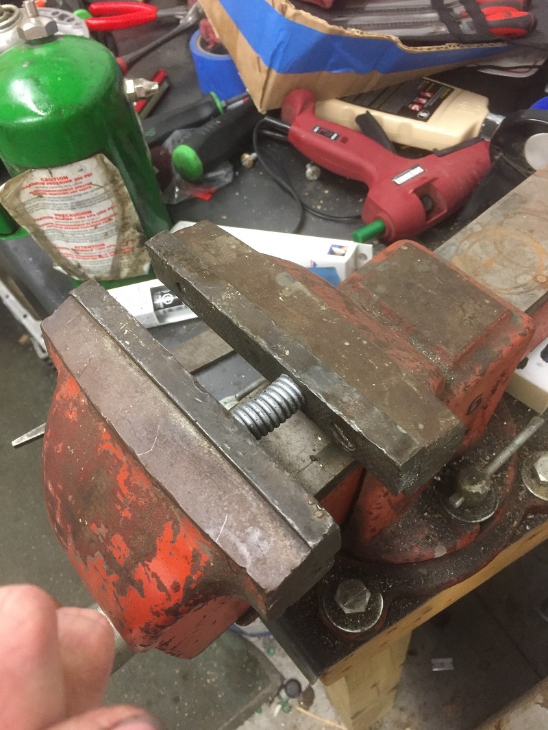
Instructions say to crunch it in a vise once
before install and the spring will take a set. Who am I to argue?
If your pump came with one, or if you can
procure one, use the stock inner spring with the transgo outer. This is more
important with higher rpm engines. If you want to deviate from this setup, Steve
V graciously did some recent testing of different spring/spacer stackups at both
min and max slide positions and posted his findings. Here's a cut and
paste of the raw data:
Stock BRF dual spring
@1.5 = 28.2lbs w/sonnax spacer 39.2lbs
@1.225= 54.6lbs w/sonnax 65.8lbs
NOYOYO spring 5500 rpm kit
@1.5 = 19.8lb w/sonnax 34.8lbs
@2.225 =62.6lbs w/sonnax 80.4lbs
NOYOYO w/ BRF inner spring
@1.5 = 26.8lbs w/sonnax 47.6lbs
@1.225= 77.8 w/sonnax 97.8lbs
The
short version: Higher RPM needs higher spring pressure to counteract
inertia/centrifugal force. Do some searching if you want to go full nerd about
it. Note that I've personally never assembled one with the "full boogie" 97.8
LBS combo but it does fit in the cavity.
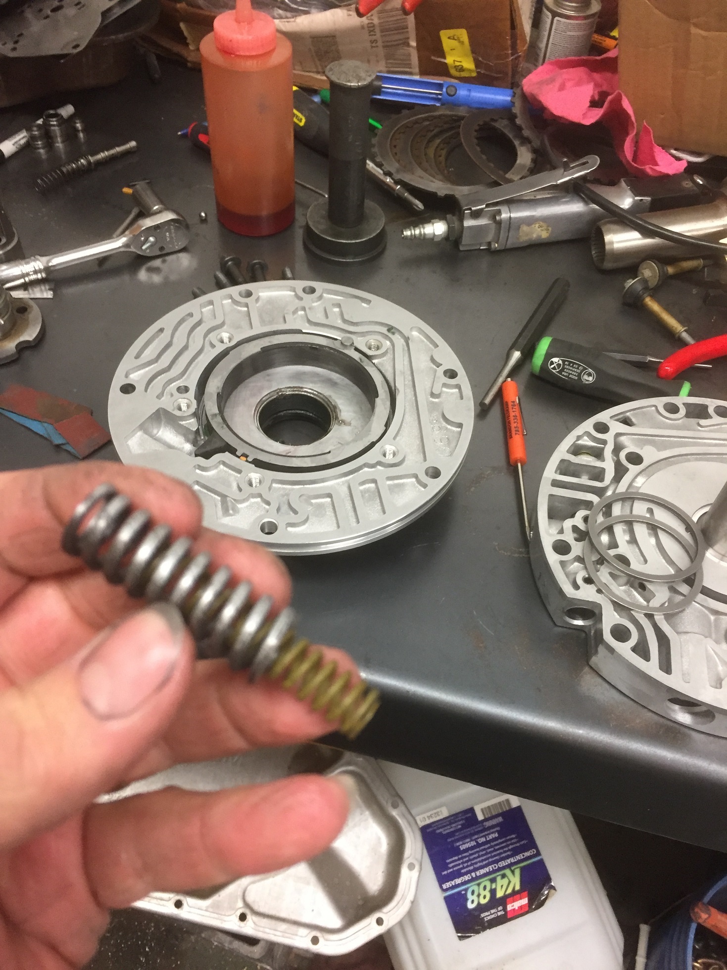
Some prefer to put both springs into a bench
vise and compress them and then carefully slide them into place. I use a
screwdriver and a cuss word or two. If you place them down against the housing
and force them in on the slide side, you won't burr up the nicely decked housing
you created earlier.
Stick the rotor guide to the rotor with some
transjel or vaseline. Then stick one of the transgo pump rings to that. Then
flip the rotor over and install into the housing.
When you install the pump vanes, pay attention
to the direction, and if they are used vanes, install them so the side that
originally contacted the rings continues to do so. (side with two shiny flats
goes inward). May have to rotate the rotor as you do this to get the lower ring
moved into a favorable angle to allow them all to fit. Then you install the top
ring. Then lube the assembly.
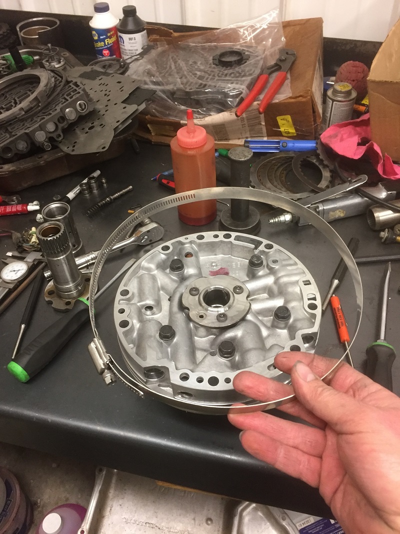
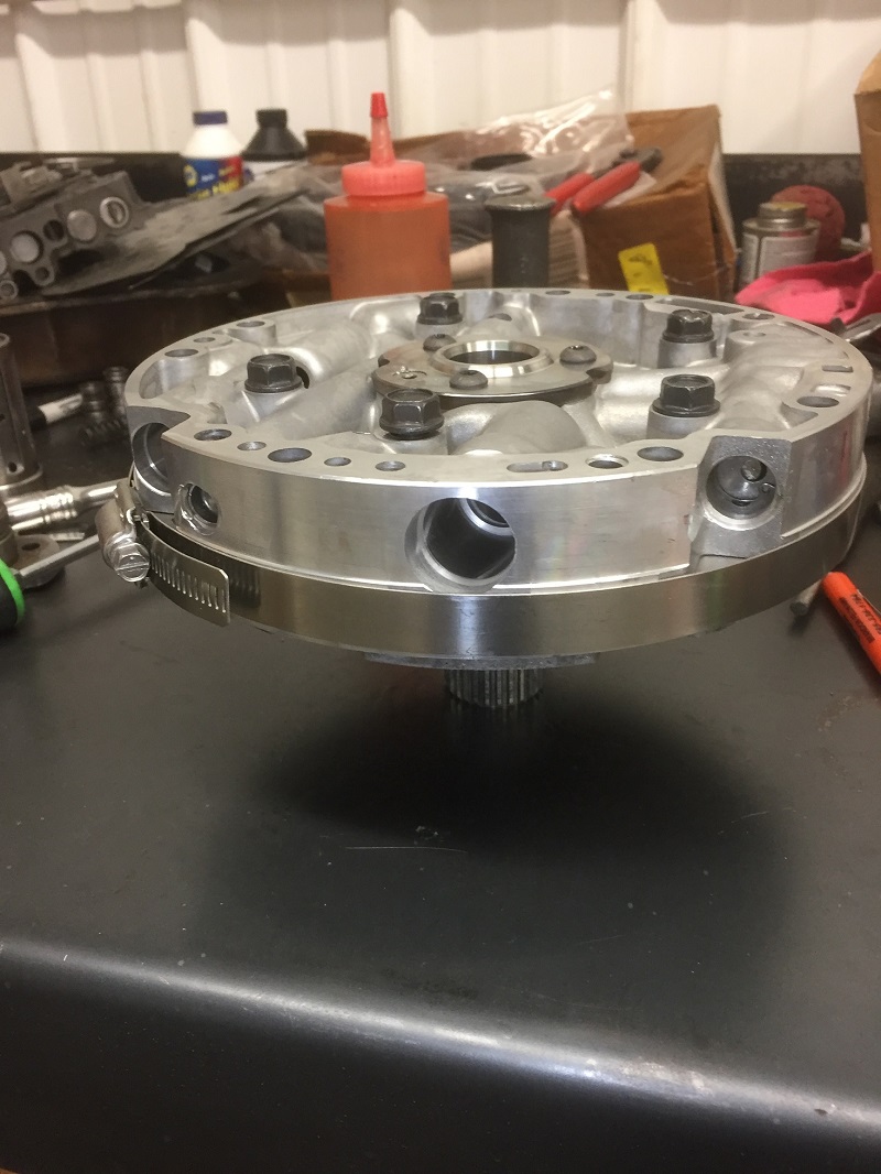
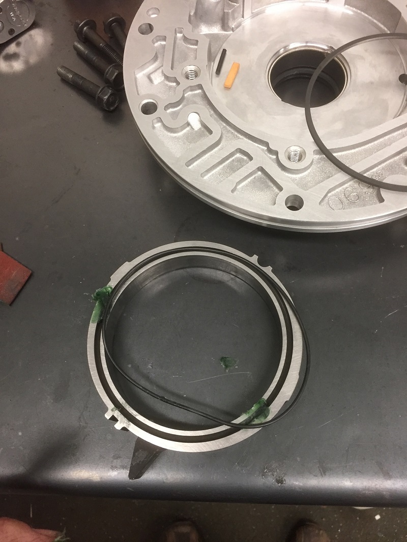
Place the stator side of the pump onto the
body side. Rotate it so all 5 bolt holes line up (only lines up one way) Pick up
the body and finger tighten all 5 bolts. The two halves must be perfectly
aligned before torquing. You can buy the factory tool, or you can use a $4 large
hose clamp as an alignment band. You can also use several smaller hose clamps
linked together. Some even drop the pump upside down into the empty trans case
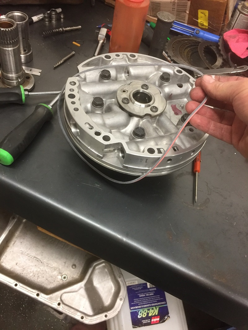
for alignment.
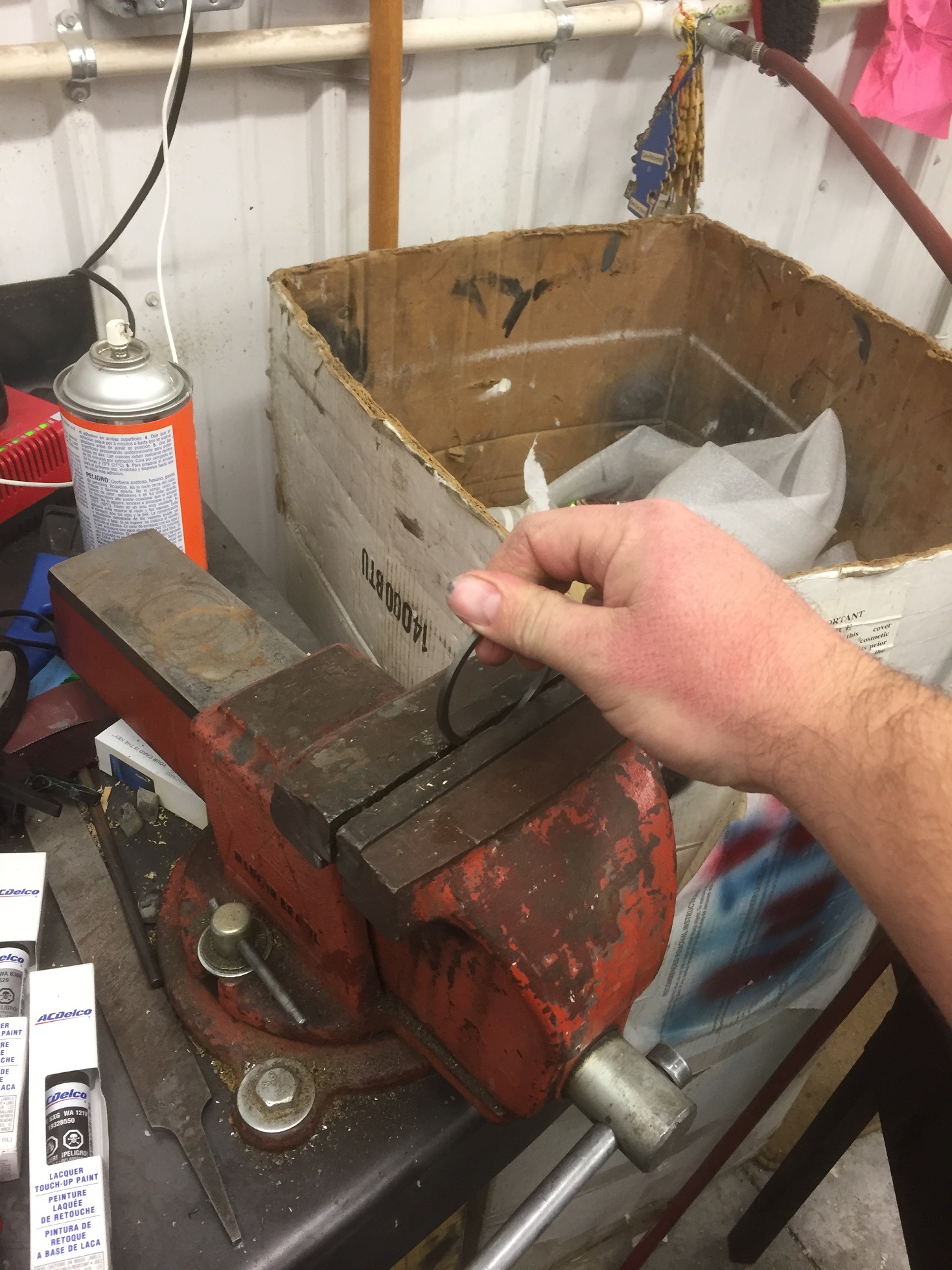
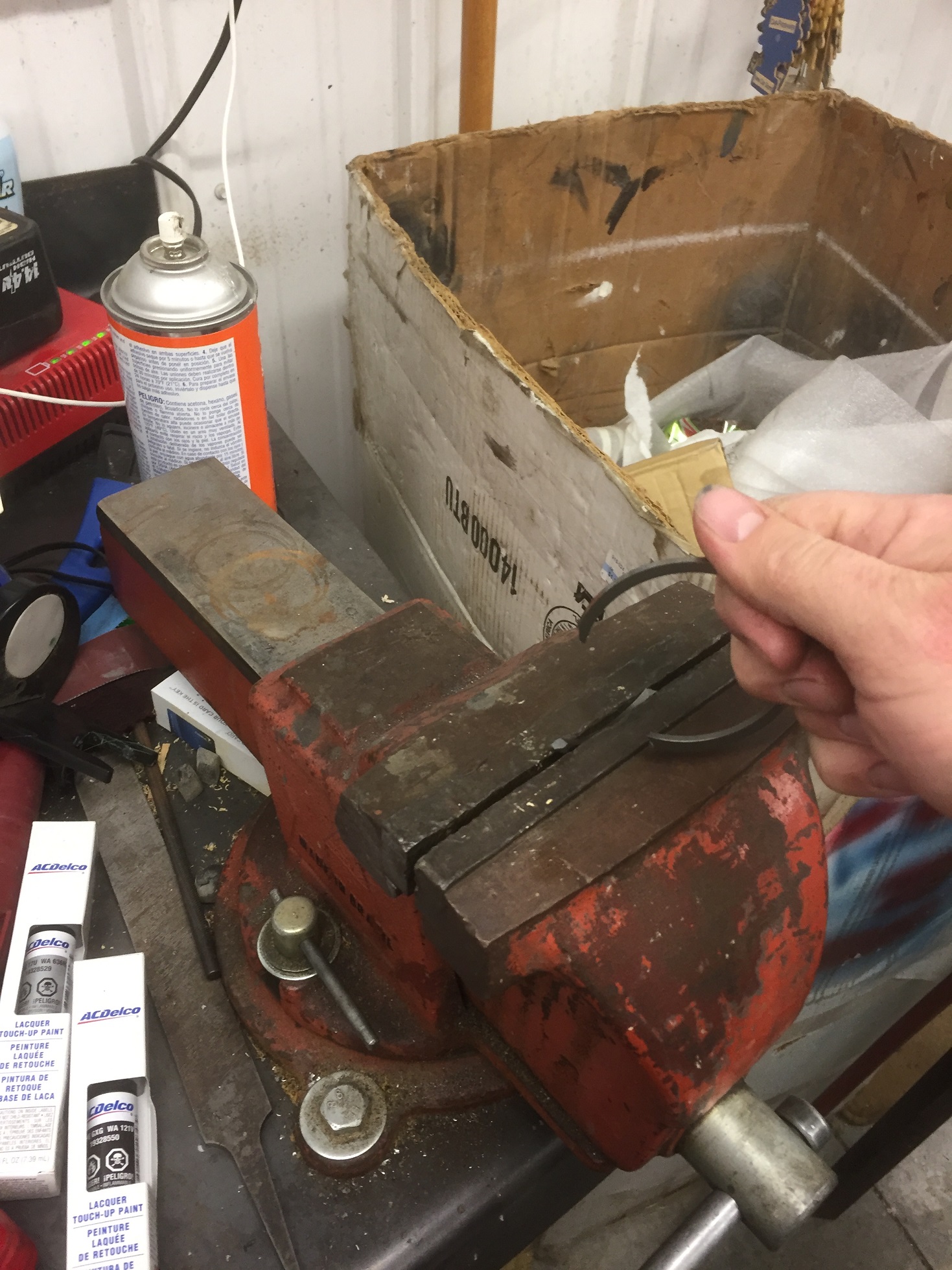
While you're doing it, you might as well line
up that drainback hole you took the time to enlarge. Photo shows the correct
position of the alignment band around both halves. Torque the 5 bolts to 18-20
ft-lbs. and remove the alignment clamp.
Install the new o-ring around the outside,
making sure it's not twisted and the painted side is out. When installing into
the trans, don't forget to stick the mickey mouse washer to the back of it and
don't forget the small pump screen filter. And that, as Smokey Yunick would say,
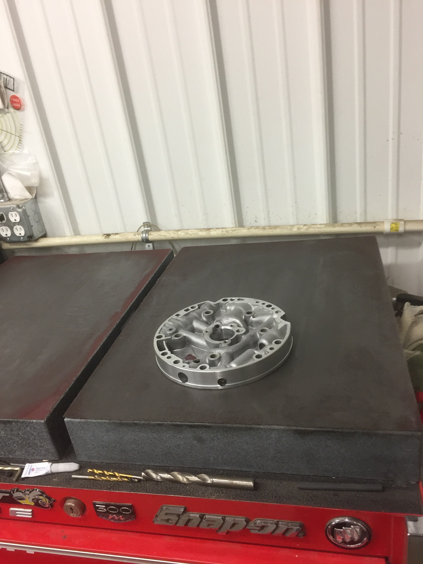
is a race ready part!