Today, we take torque converters for granted, but their implementation was a tremendous breakthrough in the development of modern automatic transmissions. Various techniques for coupling the engine to the rest of the drive train by electric and vacuum-operated clutches, fluid drive mechanisms, and Henry Ford's foot-actuated planetary drives in his Model Ts have been tried. All worked to some degree, but all had disadvantages.
The first use of hydraulic coupling to connect a powerplant to a load occurred in the early 1900s, when a German engineer coupled a ship turbine to the propeller via a fluid drive device. The same engineer also devised a coupling with an enclosed reaction unit to increase torque. This torque-improving device was the first torque converter in use and, since it incorporated the stator (reaction member) to multiply torque, it formed the basic design for all modern torque converters. The first automotive torque converter was tested in the 1920s in Germany, and torque converters were used in railcars in the 1930s. Later, a truck was produced in Sweden in the '30s with a torque converter. The first torque converter used by GM was installed in a 1949 Buick Dynaflow automatic transmission, and the first Pontiac transmission to be so equipped was the 1961 3-speed Roto Hydra-Matic. The earlier 4-speed Hydra-Matic utilized a fluid coupling, which is similar to a converter but does not utilize the third element to multiply torque.
Fluid couplings were introduced by Chrysler in 1939, GM in 1940 and Ford in 1942. They provided relatively good efficiency when coupled, but they generally did not provide the desired standing start acceleration. The GM 4-speed Hydra-Matic solved this problem by incorporating a very low first gear (3.81-3.97, depending on the model) in conjunction with the fluid coupling to improve acceleration, and this combination was used from 1940 to 1964 in Oldsmobiles, Cadillacs and Pontiacs.
The first modern GM automatic was released in 1965 as the Turbo Hydromatic, and it incorporated a three-element torque converter, three forward gears and overrunning clutches that allowed the next higher gear to pick up the load from the preceding gear. This eliminated shift timing problems that plagued some of the competing transmissions (which had to come out of a lower gear before applying power through the next higher gear). The entire line of current GM transmissions has descended from the TH-400.
HOW IT WORKS
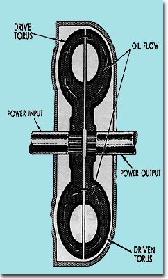
What is the difference between a fluid coupling and a torque converter, and how do they actually transfer power? We have seen depictions of power flow through a fluid coupling as tow ordinary household cooling fans facing each other. One fan is powered up, and the air it blows causes the non-powered fan to turn. The fluid coupling does operate similarly to the fan example, except that automatic transmission fluid (ATF) is the medium used to transfer power. The ATF for the fluid coupling (and torque converters) is furnished by the automatic transmission gear type oil pump. Both halves of a fluid coupling are constructed identically with flat-type vanes. (Refer to illustration No. 1 of a fluid coupling.) (It's from Page 9, '56 Hydro Shop Manual.)
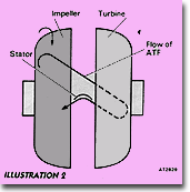
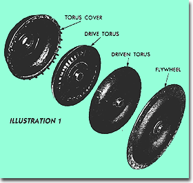
The torque converter incorporates one major change from the fluid coupling: a third element (the stator) is designed into the unit. The stator consists of a finned element that fits between the driving member (impeller) and the driven member (turbine), and it is mounted via a one way clutch to the turbine. In addition, the vanes of the impeller and turbine are curved, and are oriented differently in the two units. The curved vane construction allows the ATF to change directions rather gradually as it passes between the impeller and the turbine. This gradual change of direction imparts more force to the turbine as the oil strikes it. (See illustration No. 2 for a cutaway view of a torque converter) (Page 7E13, '71 Shop Manual)
A torque converter has the impeller connected to the engine, while the turbine is connected to the mechanical portion of the transmission. Upon engine startup, the transmission oil pump pressurizes the converter with ATF. The impeller "throws" the ATF into bucket-like receptacles of the turbine and generates some pressure on the turbine in the same direction as the impeller is turning. After striking the turbine, the ATF us deflected back toward the impeller. As the engine speed increases, additional ATF velocity develops due to impeller action, and without a stator installed, the ATF would be reflected back from the turbine to the impeller in a direction that impedes the impeller operation. With a stator installed, the stator vanes redirect the returning ATF so that it strikes the impeller elements in the correct direction. (See illustration No. 3)
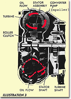
At the same time, the stator adds the energy from the returning ATF to the turbine shaft. This energy, added to the original energy transferred from the impeller to the turbine, is what causes the "torque multiplication" in a converter at low rpms. In a typical stock converter it is about a 2:1 multiplication factor. As the rpm increases, the angle of the returning oil from the turbine changes and, at some point, the stator fins begin to impede the flow of ATF. The one-way (roller) clutch in the stator allows the stator to begin to turn on the shaft so as not to affect the ATF flow. At that point, the converter is said to be "coupled," and the converter now operates at an approximate 1:1 ratio. The stock TH-400 torque converter multiples torque 2:1 at low rpm so that a moderate-ratio first gear (2.5) can be used. The torque converter multiplication and the 2.5 gear give a 5:1 stall ratio, and this combination provides excellent acceleration from a stop. Second gear is 1:5 ratio and Third is 1:1 (direct drive), so the steps between each gear are relatively small, which provides efficient and smooth shifts. Some torque multiplication also occurs in second and third gears at lower rpm.
SLIPPAGE VS. TORQUE VS. VEHICLE WEIGHT If a typical converter-equipped vehicle is held stationary by the brakes, the engine started, the transmission place in Drive, and the throttle opened, the engine will accelerate to some rpm level. This rpm point is called the stall rpm, and it's determined by two factors: the power (torque) that the engine can deliver at that rpm and the converter slippage. If a 350-inch engine can stall a given converter to 1800 rpm, a 455 engine would stall the same converter several hundred rpm higher due to the increase torque of the 455 at 1800. What about the load the converter sees? If the typical vehicle described above (with either a 350 or 455) is driven normally, it will move out briskly from a stop with minimum converter slippage. However, if a 5000-lb. trailer is connected to the vehicle, increased power will be required to move the vehicle, and the converter will slip to a higher rpm with either engine before the vehicle begins to move. This exercise illustrates that converters are sensitive to both power and the load imposed upon them. The stall rpm does not change with load because the drive train is locked when the stall rpm is determined. However, the converter coupling is sensitive to load. Thus, there can be no accurate description of the stall rpm and relative slippage of a converter unless both the low rpm engine torque and the load (vehicle weight) are known.
TORQUE CONVERTER CHARACTERISTICS
Converter Stall RPM: The engine rpm that a given engine will reach at full throttle with the drive train locked.
Converter Flash RPM: The engine rpm that a given engine will reach at full throttle at the point the vehicle begins to move with no brake application. both stall and flash must be checked from idle speed.
Converter Coupling Efficiency: The relative amount of slippage after the converter is "coupled."
The physical size of stock converters will generally affect the coupling efficiency; the larger-diameter converts usually slip less than the smaller units. However, modifications to the converter's internal design can change both the stall speed and the coupling efficiency, regardless of size. Also, the angles and shapes of the fins in the impeller, turbine and stator will have a major effect on both the coupling action and the stall speed of the converter.
In the earlier days of converters and hot rodding, the hot tip was to install a smaller converter in place of the stock unit. This allowed the engine to reach a higher rpm before the converter began to transfer enough power to move the vehicle. While this did provide some advantages of low-speed acceleration, it also caused excessive slippage at higher speeds. The slippage destroyed top speed and gas mileage, and also generated a large amount of heat in the ATF. Such converter slippage will accelerate the failure rate of most converters.
Unfortunately, many of the speed shop "universal converters" sold today are basically smaller converters with some minor construction features to enhance durability. Most are intended for the relatively low torque of a SB Chevy. While they will provide higher stall, they may slip excessively when installed in our heavier Pontiacs with the high torque generated by most larger-displacement Pontiac engines.
SELECTING A CONVERTER
As with most major components, the intended use is paramount when selecting a converter. A drag race vehicle is usually lighter, has more radical drive train gearing, less concern for transmission/fluid overheating, no concern for fuel mileage, and normally has a higher-rpm-range engine with very little low end torque. It's obvious that an optimum converter for such an application is far removed from a street or street/strip vehicle that is actually driven for normal transportation.
The typical street Pontiac has a usable power range from idle to 5500 rpm. As a stock converter will begin to transfer enough power to move the car at very low rpm, the usable rpm range is approximately 5000. If the low-speed characteristics are modified to move the idle range up by longer-duration cams, excessively large port heads, high rpm manifolds and/or large tube headers, more power is usually lost at low rpm than is gained on the top end. The usable power range becomes noticeably smaller.
If a converter that will actual stall to 3500 is installed, the usable power range is reduced to a point that normal driving becomes difficult, although optimum quarter-mile acceleration may be achieved. In order to provide the best combination of acceleration, speed and driveability, the converter should allow the engine to stall just to the beginning of the strong torque range. Any additional increase in stall rpm will begin to waste the good low rpm torque range. Additionally, the higher stall is normally accompanied by greater slippage at higher speed causing excess ATF heat, less mph and greater fuel consumption.
Another important factor of slippage is the effect on gear changes. At a shift point of 5200, the engine will drop to 3500 at the start of the next gear. If the converter is not fully coupled at that shift rpm, a loss of acceleration may occur, and by the time the converter is coupled, it is almost time to shift again (or run out of rpm in high gear). A very loose converter may improve 60-foot and eighth-mile times for a lightweight race car, and might even help with quarter mile times. However, a normal-rpm-range Pontiac street car is likely to lose performance in the quarter-mile with such a converter, and the loose converter may not all the car to run the full quarter-mile without hitting the redline.
EFFECTS OF TIGHT/LOOSE CONVERTERS
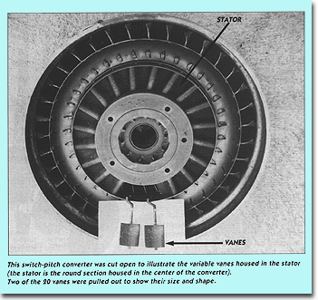
Because of the almost infinite number of combinations of engine components, gearing and vehicle weights, and the variety of available converters, it is very difficult to conduct meaningful performance test of converters. However, it is possible to demonstrate the general characteristics of converters by using a variable (switch) pitch converter-the type used in the mid-'60s on several GM full-sized 3-speed cars and mid-sized cars with 2-speed transmissions.
The switch pitch converter has a stator with variable stator vanes whose pitch (angle) can be changed by hydraulic pressure. Conventional stator vane angles are set to about 23 degrees. The TH-400 switch pitch converter vanes can be set to 18 or 26 degrees. An electric switch is used to send a 12-volt signal to an electric solenoid in the transmission (a switch was originally connected to the throttle linkage on factory applications.) The solenoid directs oil pressure to the stator clutch assembly, causing it to "switch" the stator vane positions. Most current applications of the switch pitch unit use a manually operated switch to control the switching action.
Photos were taken of an actual pitch switch converter, and careful review of these pictures will reveal damage to some of the components. (Such is life behind a good 455!) The first photo shows the impeller half of the converter with the stator sitting beside it. The second illustrates how the stator fits into the impeller half. The third is a closeup of the stator showing the individual vanes and attached cranks, and the clutch assembly that actually causes the vanes to switch position. (Two of the vanes were removed from the stator for clarity in the photos.) Except for the movable vanes, regular converters appear almost identical to this unit. Gary Carnivale, who owns a '70 LeMans coupe with a variable (switch) pitch transmission, conducted some tests several years ago with his unit. His LeMans runs high 12s/low 13s with an essentially stock 455 equipped with and 068 cam, 1.65 rocker arms, stock '71 No. 96 heads, and a 3.31 gear. He normally stages at about 1200 rpm
with the converter in the high-stall position, hits full throttle to leave and at about 3500 rpm, switches the unit to low stall. The hydraulics in the converter completes the switch prior to the 1-2 shift. This technique provides some of the benefits of a loose converter at low rpm without the slippage at higher rpm in second and third gears. Although the actual quarter-mile numbers for the tests are no longer available, Gary recalls that the switch pitch improved the ET by .15 to .2 seconds over a standard stock converter and increased mph by about one, when it was switched as described above. When the converter was left in the high-stall (loose) position for the entire quarter-mile, the ET remained about the same as in the switched position, but lost about 2 mph. When it was left in the low stall (tight) position, the LeMans lost about .25 ET and 1 to 2 mph.
The high-stall operation of the switch pitch unit is somewhat similar to the performance of the early style, small converters in that it slips continuously and loses mph. This type of performance can also be expected if a loose, SB Chevy-style unit is used with our torquey Pontiacs. The low- stall condition would be similar to what some manufactures are advertising as "mileage" converters. Properly matched and/or custom made converters for specific vehicles will approximate the performance provided by the switched condition of the switch pitch unit.
AFTERMARKET CONVERTERS
In our street/strip applications, we have never seen huge gains in performance by switching converters. The converters that were replaced were reasonably well-matched to the application, and our engines are generally lower rpm with substantial low-rpm torque, so there was less room for improvement. What we have experienced with our custom –made converters are improved driveability, easier staging at the strip, more consistency for 60-foot and the quarter-mile, and higher quarter-mile mph.
Aftermarket companies employ a wide range of techniques to improve performance including smaller converter size, different shapes and angles of fins on the pump, turbine and stator, and different positioning of the various components. The techniques used are generally regarded as company secrets and are not willingly revealed. In addition to the changes for performance, there are a wide variety of modifications and additions made for converter strength and reliability.
WHAT SHOULD YOU DO FOR A CONVERTER?
The overall performance of most stock cars with stock engines is usually best when using stock converters. The heavier cars with very high gearing (2.21-2.73) will respond well to slightly looser converters. Minor changes in camshafts that push the power range up in rpm may require a different converter. The GM L-88-style converter will work fine for both applications.
The original L-88 converter is a full-sized unit (13 inches) that will provide a stall speed several hundred rpm higher than stock, while retaining maximum reliability. Due to the lack of original L-88 units, various converter rebuilders modify stock type 13-inch converters to work similarly to an L-88. We have had excellent service from these type of units, costing in the $80 range, and have recently seen excellent performance from units costing about half of that. However, we do not have any data on the reliability of the ultra-low-cost units.
As with any major component of the drive-train, reliability, warranty and performance of the converter must be considered along with its initial cost. If a significant change in engine power/rpm characteristics is incorporated, a custom-made converter should be considered. Contact the major suppliers or manufactures of converters with your specific vehicle and engine specifications.
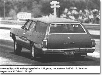
The custom converter in my '71 LeMans wagon was built my Continental Torque Converters Inc. (310-674-1072), and was designed to match the low-rpm, high torque 455 engine in the 3900-lb. vehicle. At full throttle, the brakes won't hold beyond 2300, so the actual stall is unknown. We do know the converter will flash to 2700 when accelerated from dead idle to full throttle with stick rear tires. The higher stall speed (and slightly looser coupling at idle) allows good acceleration from idle, less shock when going into drive or reverse, and good controllability when staging at the strip. However, the vehicle will creep slightly at 600 rpm in Drive, so it feels like a stock converter in normal driving.
Additional proprietary modifications to the converter and its large size (13 inches) provide relatively tight coupling at higher rpm, and these characteristics (along with a 3.55 gear) combine for a good speed. (For 12.70 ETS, the speed is about 107. For 12.50 ETs the speed is around 109, and for 12.30s, about 111. This range of performance is determined by weather, strip conditions, mufflers, and/or different test components on the wagon.) The tight coupling also helps control both engine and ATF heat as well as providing reasonable fuel mileage during extended open-road driving.
QUARTER-MILE DRIVING TECHNIQUES Many drivers bring their engines up against the converter almost to the stall point. While this may help their reaction time, it usually doesn't help the ET on milder engines. By leaving at a fast idle, or as slow as the engine will run and not bog when the throttle is quickly opened, the car may actually launch harder because the converter will flash several hundred rpm higher then the stall speed. The engine is still accelerating whe it encounters the converter load (rather than being at a fixed stall rpm), and it literally yanks the car to start.
In addition, the car stays level as opposed to twisting the left front and the right rear down, as usually happens at stall rpm. A level car will leave straighter as well as transferring weight more effectively to the rear tires for better traction. If a quicker reaction time is needed, leave earlier on the tree. Of course, if you're driving a Pro Tree with only one yellow light and/or your car is equipped with a trans brake and equipment to aid your driving at the strip, you may have no choice but to stall the converter. In all cases, stage carefully and barely turn on the second light (shallow stage). This will assure that the car is in the same position for each run, which will help consistency. It will also provide the quickest ET because the car will have a slight running start at the starting line.
My 12.40 wagon will lose .15 seconds by changing the staging position from shallow to deep. If I randomly stage between shallow and deep, the ET will vary up to .15 depending on the actual staging location, and it's impossible to bracket race with that kind of variation in ET.